Help Hub 2: MasterFrame Integrated Design
Explore how MasterFrame connects structural analysis directly with integrated design workflows for steel, concrete, connections, composite beams, timber and foundations. Learn how analysis results can flow into specialist design modules for member checking, optimisation, detailing and reanalysis within one connected MasterSeries workflow.
MasterFrame Integrated Design Modules
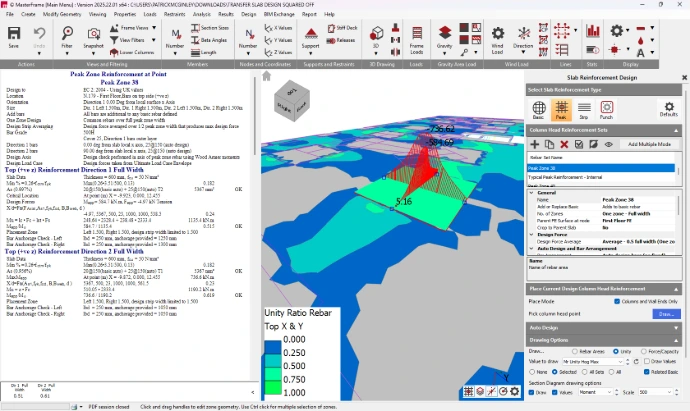


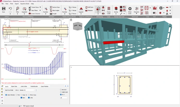
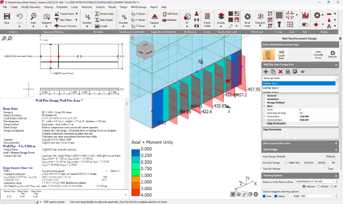
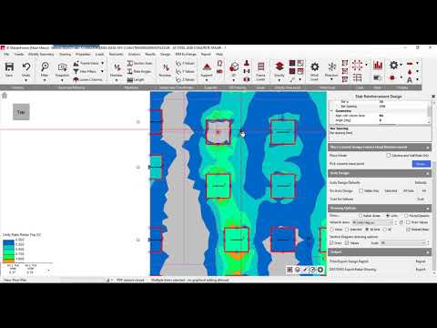
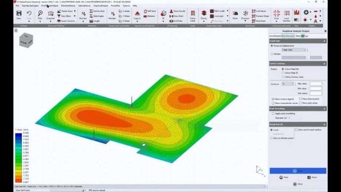
The MasterKey Concrete Slab Design module extends MasterFrame FEA to automate code-compliant reinforcement design, detailing, and verification for 2D concrete floor plates, transfer slabs, and raft foundations in accordance with Eurocode 2 and BS 8110.
Flexural and shear design is structured into four primary calculation sets: Basic Regions for establishing continuous background reinforcement mats (top T1/T2 and bottom B1/B2 layers), Peak Zones for two-way localized reinforcement over column heads and point loads with force-averaging options to smooth theoretical FE stress singularities, Strip Zones for one-way directional reinforcement along support lines or linear beam shear zones in transfer slabs, and Punching Shear Checks utilizing either the empirical Code Method or direct FE Shear Forces extraction.
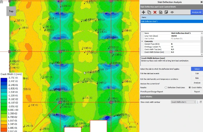
Furthermore, an integrated serviceability engine conducts non-linear, time-dependent deflection and cracking checks - accounting for creep, shrinkage, concrete cracking, and construction load-event sequencing, to accurately predict long-term slab deflections and crack widths. The software generates comprehensive engineering reports and exports design-intent rebar drawings to DXF and DWG formats.
Concrete Slab Design (FE Analysis Add-on)
- Suspended Concrete Flat Slab?
- Punching Shear at Columns or Piles?
- Ground-Bearing Concrete Raft / Piled Raft?
- Coupling Beams / Headers above Wall Openings?
- Slabs with Localized Drop Panels?
- Downstand Ribs in Ribbed or Waffle Concrete Slabs?
- Long-Term Slab Deflections and Crack Widths?
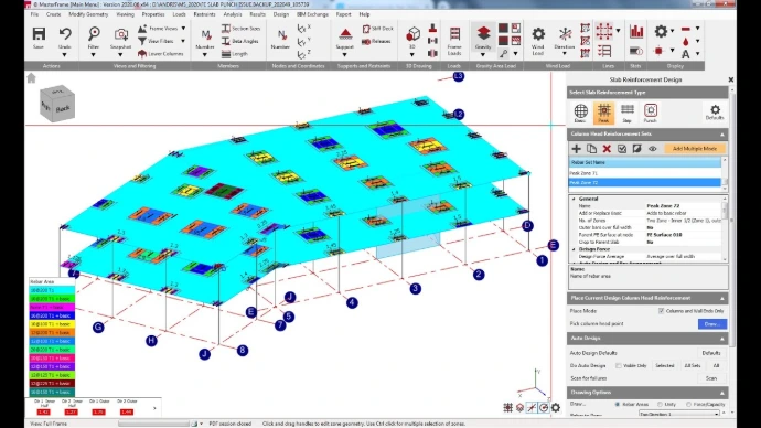

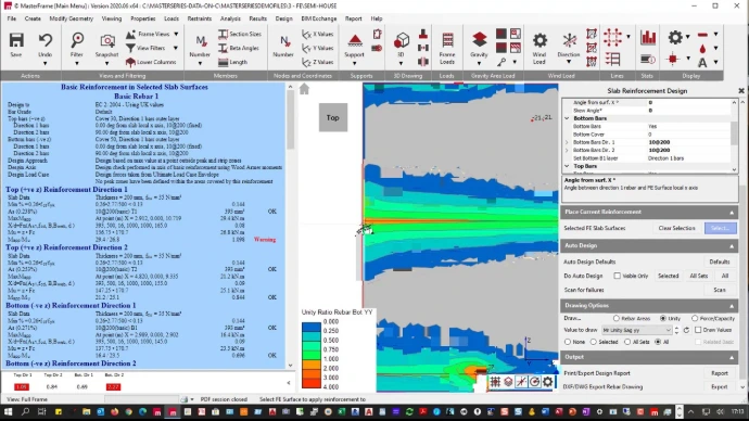
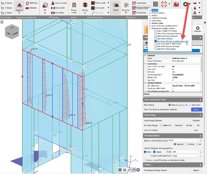
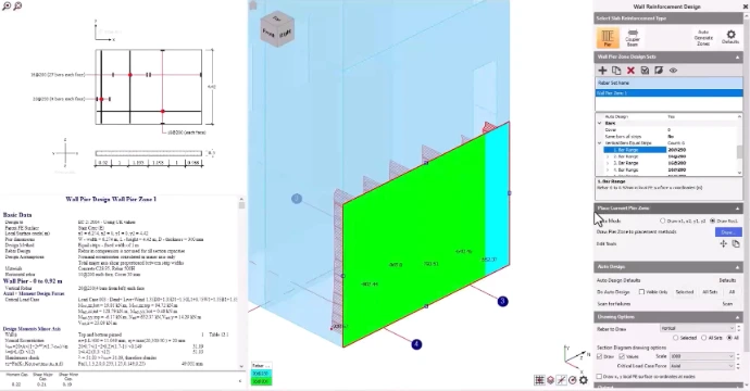
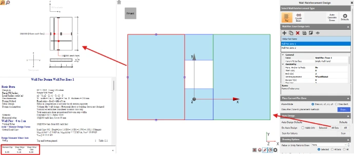
The Masterframe FEA Concrete Wall Design module (part of the MasterKey Concrete Slab and Wall Design suite) automates code-compliant design and detailing for reinforced concrete shear walls. Operating on finite element analysis results with codified concrete materials, it categorises wall geometry into two primary, independent design region types:
- Wall Piers: Vertical, uninterrupted wall sections subjected to axial load, major and minor axis bending, and horizontal shear. Piers are subdivided into sub-pier design strips (such as equal or fixed strip widths) to evaluate Ultimate Limit State force envelopes, slenderness, out-of-plane buckling, and required vertical and horizontal reinforcement.
- Coupler Beams: Horizontal bridging elements spanning between openings that experience axial compression, bending, and vertical shear. The module applies conventional beam flexural theory when span-to-depth ratios exceed 2, automatically transitioning to strut-and-tie modelling for deeper sections.
The module features auto-design capabilities, generates comprehensive calculation reports, and exports design-intent rebar layouts to DXF and DWG formats.
Concrete Wall Design (FE Analysis Add-on)

- How do I model and design Concrete Shear Walls / Core Walls in the software?
- How do I design Spandrel / Coupling Beams bridging over Door or Window Openings?
- How do I extract a single overall axial load and moment (Fy, Mz) at the base of a Shear Wall?
- Should I define Wall Piers as single continuous multi-storey units or storey-by-storey?
- Why am I getting a 'Shear Minor Capacity' failure across the wall thickness?

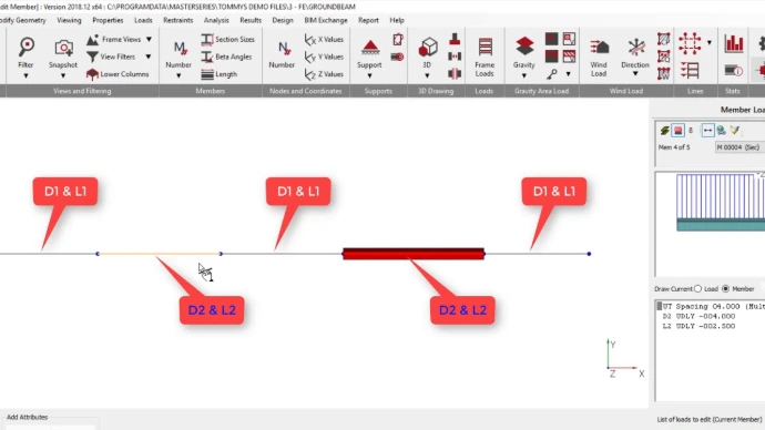
The MasterKey Concrete Beam, Column and Pad Design module integrates seamlessly with MasterFrame to automate the design, detailing, and scheduling of reinforced concrete frame elements to Eurocode 2 and BS 8110.
- For concrete beams, the software conducts flexural and shear checks, automatic bar curtailment, moment redistribution, and torsion verification across multi-span runs.
- For concrete columns, it performs first-principles axial and moment capacity checks for short or slender, braced or unbraced, and bi-axially loaded rectangular or circular cross-sections.
- For pad foundations, the module evaluates soil bearing pressures using both Eurocode 7 direct soil parameters and prescriptive safe working pressure methods, alongside checks for base uplift, sliding, overturning, and punching shear.
Engineers can group members using concrete design groups to establish uniform design defaults, optimize rebar layouts, and ensure constructability. The module generates full calculation reports, dimensioned member elevations, and exports rebar intent to DXF/DWG or MasterRC bar schedules.
- Why are bending moments low or incorrect in Attached FE Concrete Beams?
- Why does the beam design report a Minor Axis Bending or Torsion Warning?
- How do I design Inverted T-Beams and Upstand Concrete Beams?
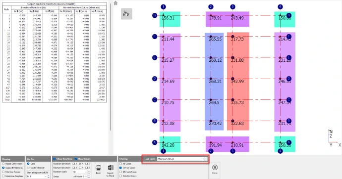
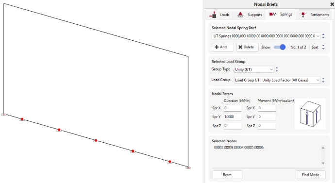
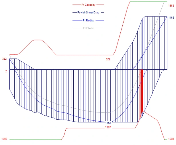
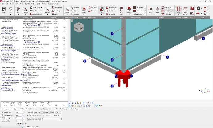
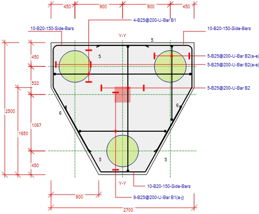
The MasterSeries (MasterRC) Pile Cap Design module is an integrated and standalone software solution for analyzing, designing, detailing, and scheduling concrete pile caps supporting 1 to 9 piles under compressive loads. Fully compliant with Eurocode 2, BS 8110, and SABS 0100 design codes, the module evaluates concentrically or bi-axially loaded, eccentric pile caps for circular and square pile arrangements. Designers can choose between standard Beam Theory (with optional Deep Beam Theory) and the Strut-and-Tie Analogy Method, or run automated comparisons to select the most economical reinforcement solution. Comprehensive verifications include vertical beam shear with enhanced shear capacity and punching shear checks at the column face and surrounding perimeters. When integrated with 3D structural models in MasterFrame, structural geometry and critical load combinations are seamlessly transferred. Finally, the software automatically details main, side, and upper reinforcement cages, generating bar bending schedules and exporting DXF/DWG CAD drawings.
- Strut and Tie (STM) Shear Warnings & Absence of Shear Links
- Concrete Compression Warnings at the Column Node (CCC Node)
- Sizing Pile Caps for Multiple Columns or Lift Pits
- Sizing Overall Dimensions & Accounting for Construction Tolerances (75mm)
- Punching Shear Checks (Column Head vs. Individual Piles)
- Lateral Forces, Moments, and Net Tension (Uplift)
- Fixed Bar Spacing (Pitch) Increments

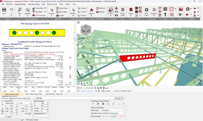
The MasterKey Steel Design module (integrated with MasterFrame and MasterPort) performs code-compliant structural design checks across a wide range of steel cross-sections, fabricated elements, and structural member types. It supports standard rolled open profiles - such as Universal Beams (UB), Universal Columns (UC), RSJs, IPE, HE, HL, HD, IPN, W-shapes, equal and unequal angles, channels/PFCs, tee sections, and flat bars, as well as closed hollow sections including CHS, SHS, and RHS. Beyond standard shapes, the software handles complex and fabricated elements, including cellular beams with regular web openings, beams with discrete/isolated web openings, welded plate girders, haunched and tapered I-sections, compound sections reinforced with top or bottom flange plates or secondary channels/members, and custom user-defined section libraries adhering to standard geometric properties. Within 2D and 3D models, these sections can be assigned and checked across various structural roles, including continuous multi-storey columns, floor and roof beams, portal frame rafters and eaves, trusses, and bracing struts or ties.

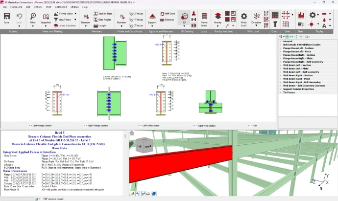
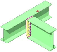
The MasterKey: Moment and Simple Connections module provides an interactive steel joint design environment fully aligned with SCI Green Book guidance, Eurocode 3 (BS EN 1993-1-8), and BS 5950. Capable of designing up to 25 standard joint types, the software functions as either a standalone tool or a fully integrated module within MasterFrame.
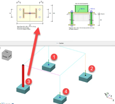
For simple connections, it evaluates nominally pinned, shear-only details including flexible end plates, fin plates, web angle cleats, baseplates, and bracing configurations. For moment connections, it checks rigid joints - such as eaves haunches, apex joints, and splices, subjected to major axis bending, vertical shear, and axial forces using codified component-based methods.
Key features include an interactive graphical editor, real-time detailing checks, automated failure scanning, and customizable design templates. When integrated with MasterFrame, it automatically synchronizes geometry and force combinations across all load cases. Additionally, the module exports dimensioned CAD drawings and seamlessly links to IDEA StatiCa for non-standard joint configurations.
The MasterSeries Composite Design module provides analysis and optimisation for simply supported composite floor beams, available both as a standalone tool (MasterBeam) and integrated within full 3D structural models in MasterFrame. The software complies with Eurocode 4 (EN 1994-1-1) and BS 5950-3+A1, incorporating relevant SCI publications and NCCI guidance rules.
Engineers can design primary, secondary, and mixed primary-secondary beams using profiled metal decking, solid concrete, or precast hollow-core slabs. Supported section types include rolled I-sections, channels, built-up asymmetric beams, cellular members, and slimfloor arrangements.
The module automatically assesses both unpropped/propped construction-stage (non-composite) and final-stage (composite) performance. Critical verifications cover moment and shear capacity, partial shear stud connections, transverse reinforcement, web openings with stiffeners, staged deflections, and natural frequency checks. When integrated with MasterFrame, section sizes, floor loads, and design forces link dynamically with the global 3D analysis, automatically recalculating member stiffnesses across staged loading combinations.

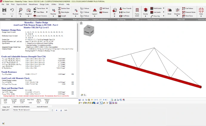
The MasterKey Timber Design module delivers automated and manual structural design for timber beams, columns, joists, and roof trusses. Operating as a standalone tool or seamlessly integrated within the MasterFrame multi-material modelling environment, it directly imports axial forces, bending moments, shear forces, and deflections calculated during frame analysis.Key features of the module include:
- Design Codes: Fully supports Eurocode 5 (BS EN 1995-1-1) with regional National Annexes as well as British Standard BS 5268 Permissible Stress Design.
- Section Types: Models solid timber (sawn, planed, regularized), glued laminated timber (glulam), and flitched timber beams reinforced with steel plates.
- Serviceability Checks: Evaluates instantaneous and long-term creep deflections (kdef) by modifying the mean modulus of elasticity (Emean,fin) and adjusting serviceability load case factors.
- Automated Sizing: Features an Auto Design engine to size members automatically across the structural frame while displaying clear unity ratios and interactive calculation briefs