T01-7 Steel Truss Design
Introduction
MasterFrame is a piece of advanced structural frame analysis software that allows you to analyse everything to beams, and trusses to multi-storey frames and complex 3D models in any type of material.
MasterKey Steel Design allows for the design of members in steel structures analysed using MasterFrame, or MasterPort to the BS, Euro or SABS codes.
If you do not have access to any of this software, please contact (Support) us for a 14-day free trial to learn how it can benefit you and your business.
Overview & Outcome
In this tutorial, we will undertake the development and design of a 3-bay portal frame with the aim of providing you with a solid understanding of:
- Truss frame generation
- Loading & analysis
- Design of steel members
- Viewing and printing the results
Loading MasterFrame
To start this tutorial, launch the main program of MasterSeries. While standing on the Programs tab, select the MasterFrame from the Integrated Analysis & Design filed.

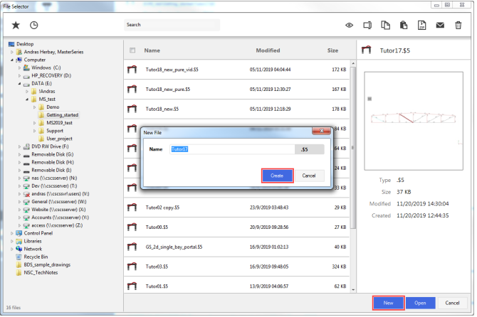
The File Selector Dialogue
The Frame Generation Menu
The Frame Generation Menu (Frame Wizard) is now displayed as shown.
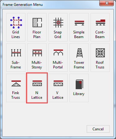
To generate our start-up frame, select the N Lattice button.
For More information Click 📑 Starting a new Frame
This tutorial describes some of the basic techniques used in MasterFrame. Please take a few minutes to familiarise yourself with the various frame viewing tools; editing and data input methods and find how you can use the modify geometry area to select members.
The Start-up Frame
The lattice truss frame pre-processor is now displayed.
From the top toolbar select the
Length ( ) to display the member lengths from the Members group to see the actual length of
our members.
) to display the member lengths from the Members group to see the actual length of
our members.
Place the beam in front view by
selecting the Front side of the
viewing cube ( ).
).
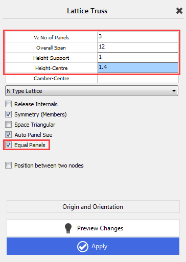
Click on ½ No of Panels and type in 3.
As we change the input in the
pre-processor the graphical display is always updated. This is because the Preview Changes (
 ) button is depressed.
Set the Overall Span to 12 m.
As our truss has varying height, we now change the Height-Support to 1 m and the Height-Centre to 1.4 m.
To keep the panels at an even length, check in the Equal Panels checkbox.
Select Apply ( ) to generate the frame. The frame now turns from grey to
black as it has been created.
) to generate the frame. The frame now turns from grey to
black as it has been created.
Close the Lattice Truss wizard by clicking on the X beside the title.
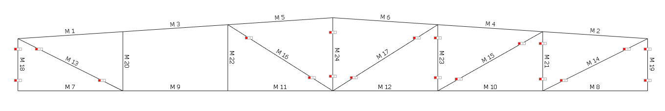
Editing the Geometry
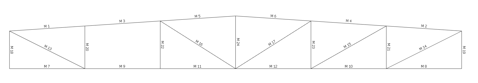
From the top toolbar turn off the member Lengths
(
) and turn on the Number
( ) in the Members
group to see the numbers of our members.
) in the Members
group to see the numbers of our members.
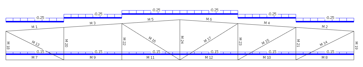
From the Modify Geometry menu, select the Delete Members, FE Surfaces, Grid Lines and then select M15 from the graphical area.
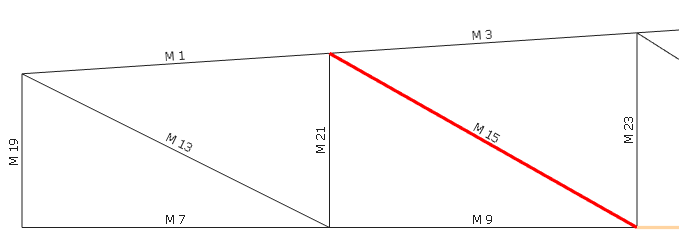
Select Apply to delete the selected member.
Close the Delete Members, FE Surfaces, Grid Lines dialogue by clicking on the X.
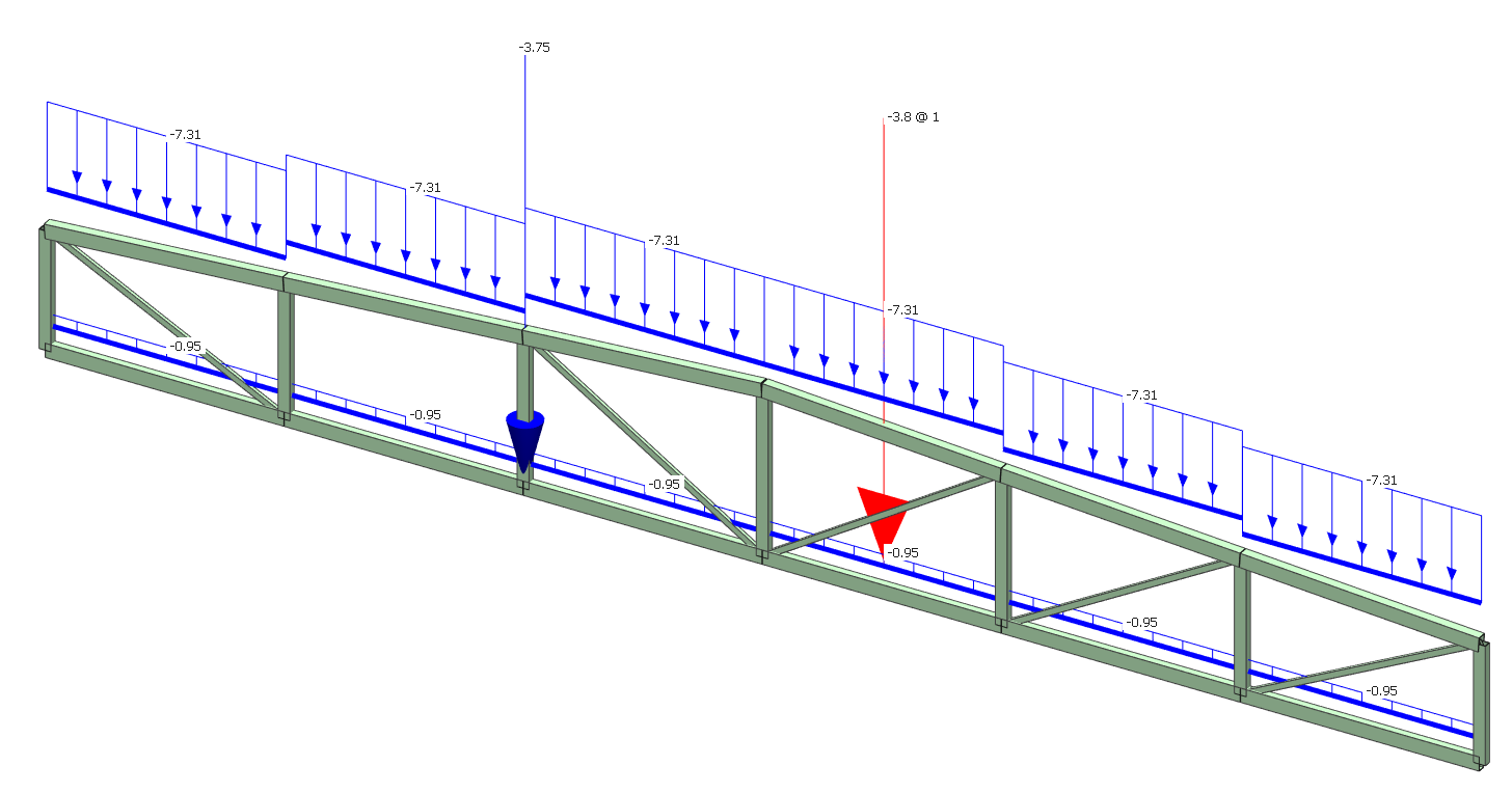
Applying Member Loading
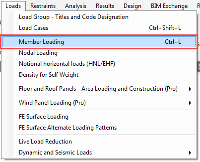
To apply loading to a member, select Member Loading from the Loads menu.
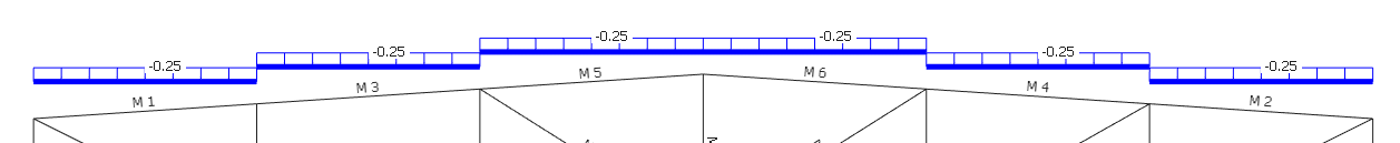
Select M1 and click on the UDLY (
 ) button (bottom left of the screen) twice to add two uniform distributed load definitions.
The list of loads edit box now has two loads in it. Both loads are D1 UDLY -000.000 which means both of them assigned to the D1 dead load group, both of them uniform distributed load in the Y-Axis and acting downward.
We now need to edit these
loads.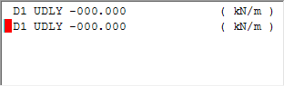
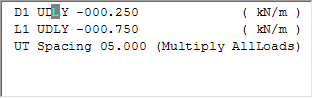
Pick the upper of the two loads to set the cursor focus to it and change the load to D1 UDLY -000.250 (kN/m) by overtyping the - 000.000 value.
Next, pick the second load or move your cursor along to it and change the load to L1 UDLY -000.750 (kN/m) by overtyping D1 with L1 to assign the load to the L1 live load group and overtyping -000.000 value with -000.750.
Change the editing method from Edit Member (
 ) mode to Edit and
Paste (
) mode to Edit and
Paste (
 ) mode and copy the loads onto all of the roof members by clicking on each of them in turn.
Remaining in Edit and Paste (
) editing mode, edit the loads in the list (palette) to D1 UDLY -000.150 (kN/m) and L1 UDLY -000.500 (kN/m).
Now apply these loads onto the bottom chord members.
Return to Edit Member ( ) mode and then select the M12 member.
Click PY ( ) button to add a new point load to the list.
Place the cursor on the new PY load and change the load to L1 PY -002.500 1.000 to assign to load to the L1 live load group and set the intensity and the position.
This will set the load as a 2.5 kN load acting at a point 1 meter along a member.
Nodal Point Load
When a node is applied at a nod it is better to apply it as a nodal load rather than at 0 meters along a member. This way the nodal load does not apply a high shear load onto the beam.
Select Nodal Loading from the Loads menu.
From the top toolbar turn off the member Number ( ) in the Members group and turn on the nodes Number ( ) in the Nodes and Coordinates group to see the numbers of the nodes.
Select node (3) from the graphical area.
In the FY textbox type -2.5 to apply a vertically downward point load of 2.5 kN and then change the load group to Live (L) L1: Live Load.
Adjust the Set load scale to a value of 2 to make the nodal load visible.
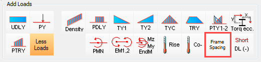
Frame Spacing
The frame spacing has the effect of multiplying all loads – in the load list that are below it – by a specified factor.
Select Member Loading from the Loads menu.
Change to Edit and Paste (
) editing mode and select the Add/Delete option.
Click on More Loads button to see all of the loading types and click button to add a new frame spacing to the list.
The list of loads screen should now have the UT Spacing 01.000 along with the two previous loads.
Change the UT Spacing to 05.000.
As we would like to add only
the Frame Spacing to the
previously defined loading definitions, we have to delete the other two loads
from the list using the Delete
Current Load (
 ) button.
As we are in Edit and Paste (
) mode, these loads are not applied to any member. The loads
will need to be applied across the top members of the truss.
Select all the top members to apply the load to them.
Return to Edit Member (
) mode and click on any of the members to view the loads
applied to them.
Close the Member Loads dialogue by clicking on the X.
Applying Density (Self-weight)
Self-weight of structural members is automatically included as a default set up.
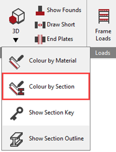
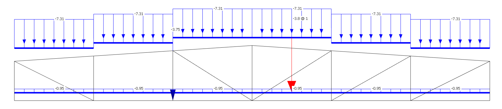
The loadings due to self-weight
can be viewed in the Frame Loads
(
 ) dialogue, by turning off all other loads except the Draw Density (Selfweight) Loads (
 ) button.
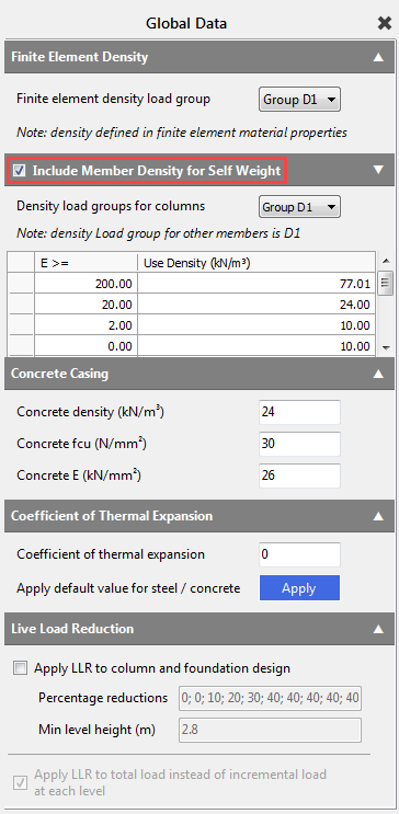
The values for self-weight can be checked by going to Loads > Density for Self Weight. To ensure that the self-weight is included, make sure the Include Member Density for Self Weight checkbox is ticked. The default load group of the self-weight is the D1, but using the drop-down menu we can modify it.
Adding Section Sizes
As we did not define the section sizes during the multi-storey frame generation processor, now we have to add some preliminary section sizes to the frame.
From the Properties file menu, select Member Sections Materials.
From the top toolbar, turn on
member Number (
).
Select M1 to make it the current member.
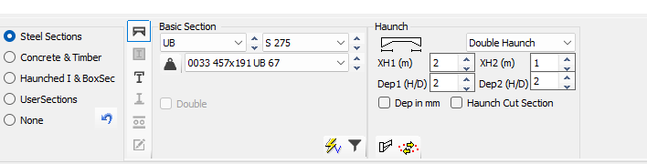
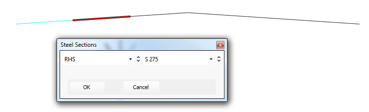
From the bottom dialogue, select Steel Sections and then from the three drop lists, select RHS, S275, and 50x30x3.2 RHS 3.61.
This section has now been applied to M1.
Change the editing method from Edit Member (
) mode to Edit and
Paste (
) mode.
Window all members to apply the chosen section to the whole truss.
Close the Member Section Properties dialogue by clicking on the X.
Member Releases
From the Restraints menu, select Member End Releases.
Select to release the Minor and Major Axes only.
Click on the top and bottom of all of the vertical and diagonal members, except M20 and M22. M3, M9, M20 and M22 panel will be a rigid Vierendeel truss as we have no triangulation.
Nodal Supports
The N Lattice Truss wizard already defined a Pinned (dX, dY, dZ) nodal support on the left-hand bottom point of the truss (node 1) and a Roller (dY) on the right-hand bottom point of the truss (node 7).
In this tutorial, we will not change the support condition, but introduce the nodal information area, and how to view the support conditions.
From the Restraints file menu, select Nodal Static Supports.
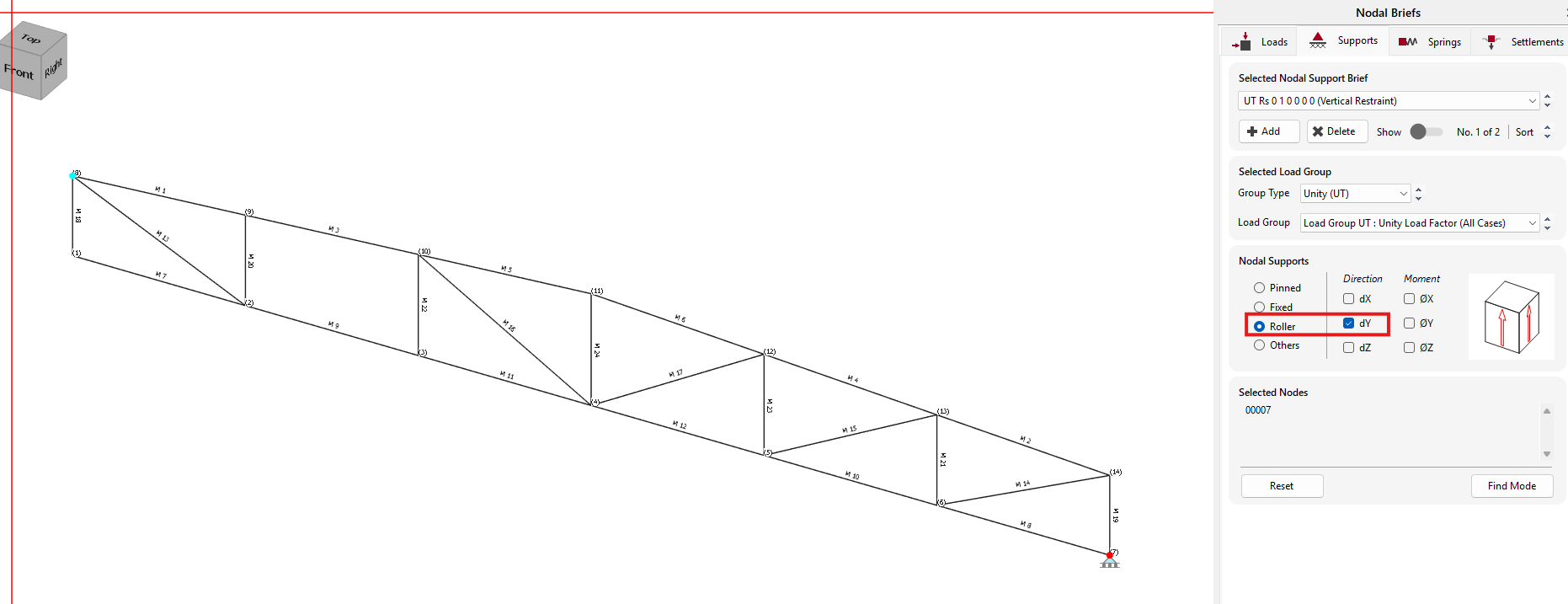
Using the dropdown list we can change between the created support conditions.
List of nodes edit box shows the number of the nodes where the selected support is applied.
Each support is graphically represented on the structural model.
TIP! If you view the frame
in Orthogonal view (instead of front view) by selecting the home button
. Then you get a better idea of the restraints applied on each
node
.
Close the dialogue by clicking
on the Close (
 ) button.
Member Viewing Groups
Member Viewing Groups allow you to filter the members displayed. When you come to design, these members can be designed for the worst loading case for the whole group.
Select Member Viewing Groups from the Viewing menu.
Click in the title edit box and type Top Boom for the first group.
Select the Add/Remove items (
 ) button and then select the top members (M1-M6).
Add a new group using the Add New Group (
 ) button.
- Give the group the title Bottom Boom and select all the bottom members (M7–M12).
- Create a new group named Vertical and select all the vertical members (M18–M24).
- Create the last group, named Inclined, and select the internal inclined members (M13 – M17).
Load Cases
Design Code
We need to make sure we are designing to Eurocode.
On the top menu, go to Design > Design Code and check the selected code which should be Eurocode. If not, please select it.
If you are asked “Do you wish to change the Loading Cases in accordance with the design code change” select Yes.
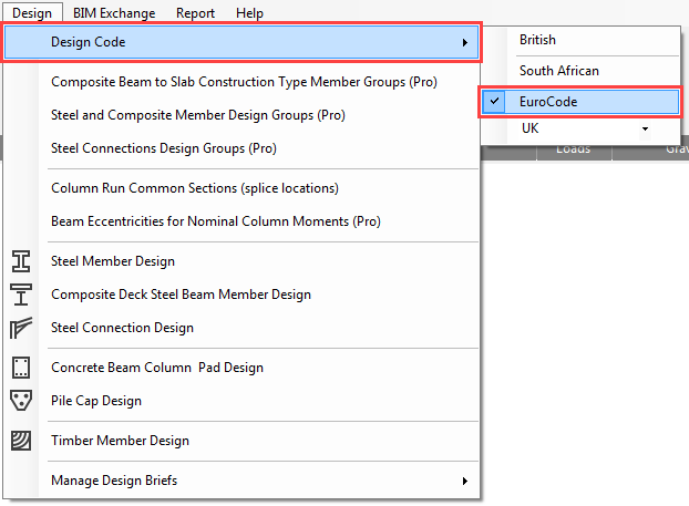
Go again to the Design > Design Code and check the national annex which should be the UK. If not, please select it.
If you are asked “Do you wish to change the Loading Cases in accordance with the design code change” select Yes.
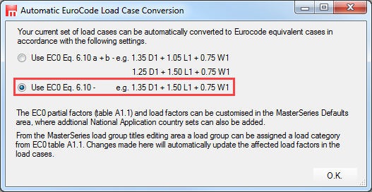
If you are asked which EC0 Eq. 6.10 set to use, choose the lower option 6.10.
Loading Cases
From the Loads menu, select Load Cases.
By default, there are already two (or three in case of using EC0 Eq. 6.10 a+b by default) combinations of actions and case titles generated.
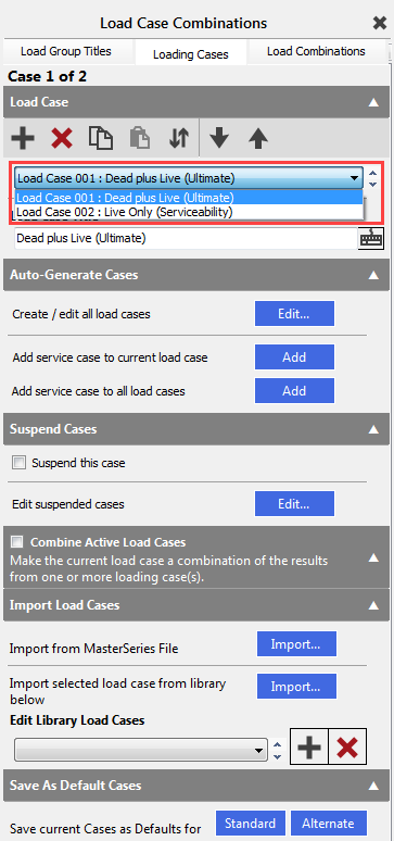
- Load Case 001: Dead plus Live (Ultimate) (Permanent Plus Variable)
- Load Case 002: Live Only (Serviceability) (Variable Only)
In this tab, we have the facilities to manage loading cases and define titles for them. However, for this example, we will retain the default loading cases and titles.
Analysing the Frame
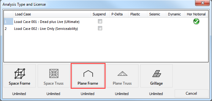
From the top menu select Analysis, then Static Analysis.
The file will be saved automatically and the Analysis Type and License toolbar will now appear.
As our frame is semi-rigid we will use frame analysis.
Select Plane Frame ( ) and the frame will be
analysed.
) and the frame will be
analysed.
Viewing Graphic Results
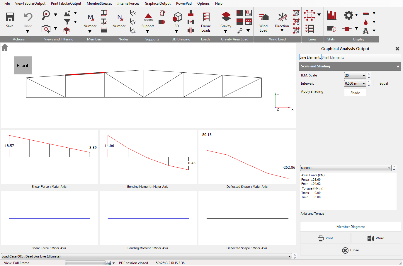
From the Results file menu select Graphical Analysis Results.
Place the beam in front view by
selecting the Front side of the
viewing cube (
).
Select Bending Moment. We have no bending about the Minor axis so select Major Axis Only on the right-hand panel.
Select Show Values and adjust the B.M. scale if it is necessary.
Using the drop list, at the bottom of the screen, we can select and view each of the Load Cases including the envelopes.
Select the Member Diagrams button on the bottom of the right hand dialogue.
This displays all the diagrams for the current loading case of the current member on a single screen, together with the torque and axial local values.
The current member can select in the graphical area or from the member droplist.
Printing Graphic Results
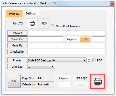
Select the Print ( ) button.
The Job Reference form enables you to finalise the job details on your printout just before printing them.
The Job Reference text boxes enable you to edit the job reference details that will appear in the printout.
While viewing the preview you can use all the tools on the top toolbar and the side menu, including zooming, panning, scaling and font sizes.
You can change the printer from the dropdown list of printers and alter the page orientation from portrait to landscape.
Select the Printer ( ) button.
Close the Job Reference dialogue by clicking on the X.
Select the Close button to exit the Graphical Analysis Output window.
Viewing Text Results
From the Results file menu select Tabular Analysis Results. This will take you into the Nodal Deflections table.
The options in the lower part of the screen enable you to control the results being displayed and are very easy to use. When there is a large amount of data the vertical scroll bar controls the view.
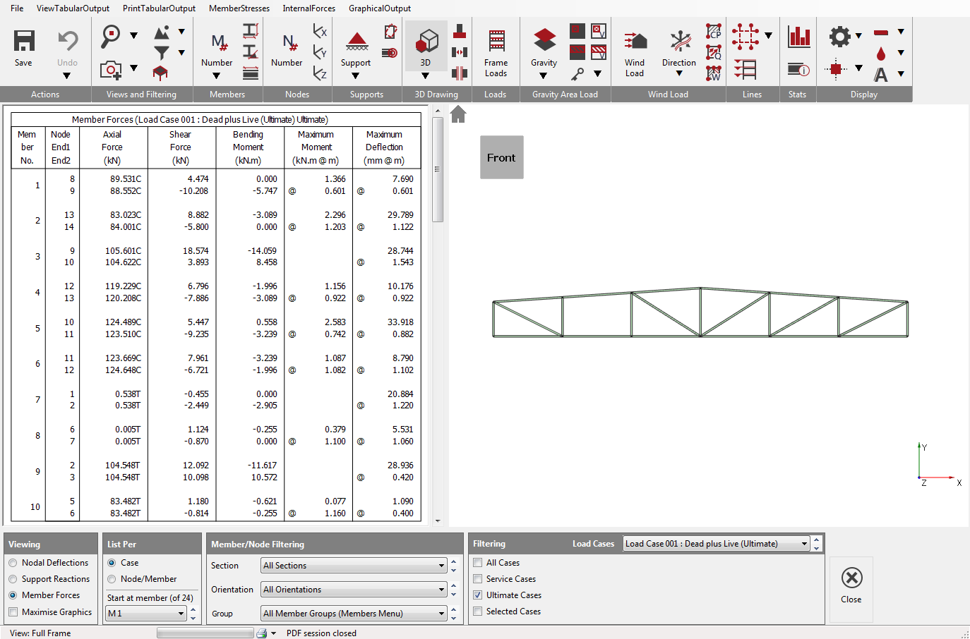
The standard method of viewing results is List per Case. This only display results in one loading case at a time. The other method is to List per Node/Member. This is useful to compare results for different loading cases for the same node or member as shown here.
Experiment with the various options to display the results.
To close Tabular Analysis Results select the Close (
) button.
Steel Design
Now we will design the steel beam.
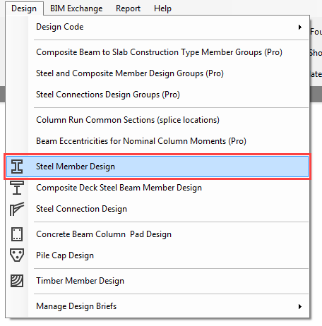
From the Design file menu, select the Steel Member Design option and select all the members in the frame, by windowing them.
From the Integrated Design menu, select the Auto Check–Group Check option.
The Auto Check – Group Check will carry out quick local and overall capacity design checks on all the members selected, assuming their effective lengths to be the full length of each member.
This will give you an indication as to which members are already satisfactorily sized.
The results of the Auto Check – Group Check are colour coded as follows:
1. Red members are locally overstressed
2. Cyan members require additional lateral restraints
3. Black members pass the local and buckling checks
4. Grey members are not checked (e.g. concrete or sections not licensed)
The above results indicate that some members are under-sized. We will use the Axially Loaded Members with Moments check to select suitable sections.
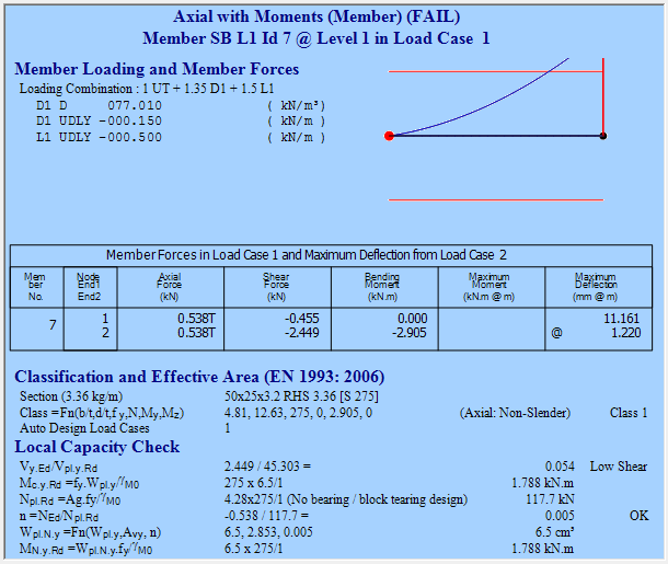
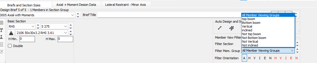
Select Axially Loaded Members with Moments from the Integrated Design menu.
The Apply-to mode ( ) (bottom left of frame graphics window) should be automatically selected. If not, select this mode. Apply the brief to one of the failing members by clicking on it.
The results from this check are displayed in the main design output window. The cyan coloured background indicates that there is a design failure.
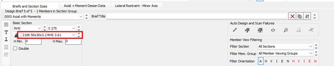
On the Briefs and section Sizes tab, use the sections drop list to scroll through and find a section size that passe.
Alternatively, you can design the section automatically.
Reset the section size and
click on the Auto size the selected member
( ) button, and MasterSeries
will size the member for you.
) button, and MasterSeries
will size the member for you.
Using Automatic Design
Placing of design briefs – rather than place design briefs on all members manually, we will now do this automatically.
First delete any additional Axially Loaded Members with Moments
briefs you have created by clicking on the Delete current brief ( ) button.
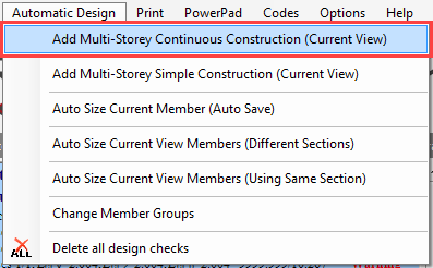
From the main Automatic Design menu, select Add Multi-Storey Continuous Construction (Current View).
MasterSeries will apply an Axially Loaded Members with Moments check to all the currently visible members of the frame. Thus we should end up with 24 individual design checks.
We will now design each viewing group of members in turn, with each group having the same section size.
Click on the Sort by weight (
 ) button so automatic design will use the lightest section
size which passes the check.
) button so automatic design will use the lightest section
size which passes the check.
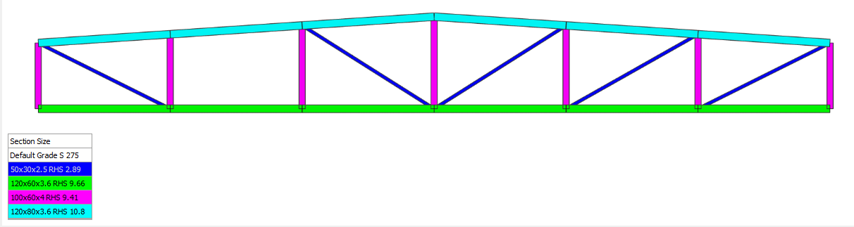
Design the Top Boom
Change the Member Viewing Group to Top Boom from the drop list – All Member Groups (Members Menu) at the bottom of the screen.
 change
Select to Auto size all visible members to use the same section
(
 ).
).
Confirm that you wish to use the RHS sections and steel grade shown. The members are automatically sized for the lightest section that satisfies all 6 members.
Design the Remaining Member Groups
Repeat this process for the remaining member groups (bottom boom, vertical and inclined members).
Change the Member Viewing Group from Top Boom to the next one.
Select to Auto size all visible members to use the same section
(
).
After finished the the design the remaining member groups, set the member groups back to All Member Groups (Members Menu) in the drop list showing the whole frame. Since the section sizes have been altered, we need to re-analyse the frame and carry out a final check on all members.
Click on the Re-Analyse ( ) button next to the Auto Size
buttons. The frame is quickly re-analysed.
) button next to the Auto Size
buttons. The frame is quickly re-analysed.
Click on the Scan for failures ( ) button. This will check all the design briefs already set
up, and highlight any briefs which may fail after re-analysis.
) button. This will check all the design briefs already set
up, and highlight any briefs which may fail after re-analysis.
If a failure is discovered you will have to adjust the section size of the member(s), re-analyse the frame, and check for failures.
Repeat this process until you have no failures.
Printing the Design Output
Select Print Design Output, from the Print menu.
The print manager will appear at the bottom of the screen listing all the design checks applied to the beam.
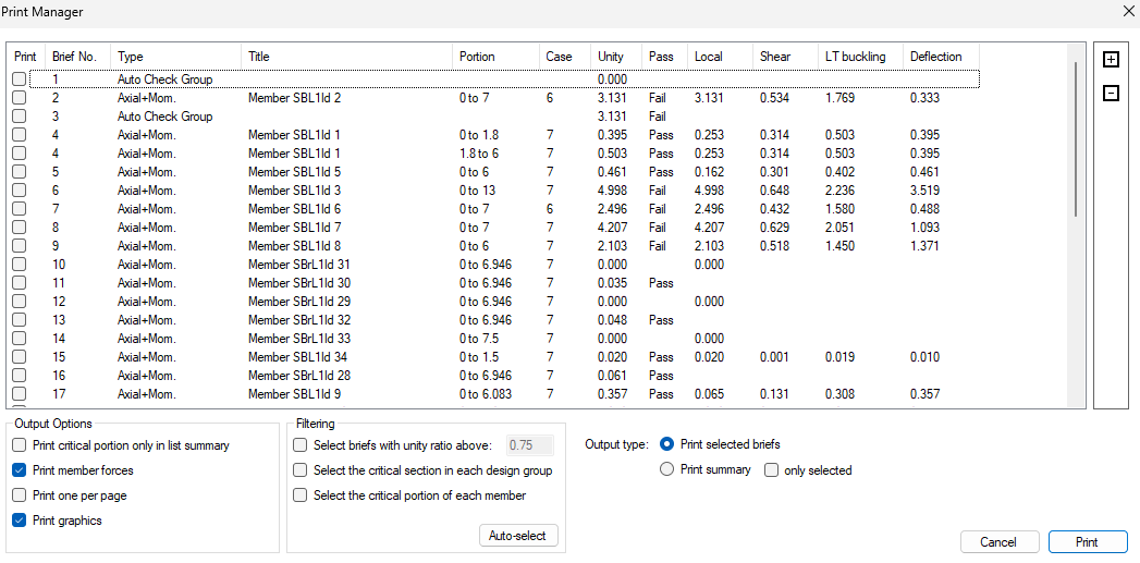
Click on the Include All button to highlight all design checks and display their maximum unity ratios.
Check the Critical from each section size (per Design Group) checkbox and click on the AutoSelect button.
This reduces the currently selected checks to the most critical member from each section sizes.
There are two options available:
· Print List (Summary): print the list that is displayed in the print manager window
· Print Selected Checks: print full detail for the design output for the check highlighted in the list
The printed design output appears in exactly the same format as shown on the screen.
Close the Steel design by clicking on the main X.
If prompted, save the file.
End of Tutorial