T01-1 MasterFrame Tutorial
Simple Steel Beam Design to Eurocode 3
📑 Introduction to MasterFrame
Previous Versions
For version 2020.01 - https://files.masterseries.com/Tutorials/T01-1%20MasterFrame%20-%20Simple%20Steel%20Beam%20Design.pdf

Introduction
MasterFrame is a piece of advanced structural frame analysis software that allows you to analyse everything to beams, and trusses to multi-storey frames and complex 3D models in any type of material.
MasterKey Steel Design allows for the design of members in steel structures analysed using MasterFrame, or MasterPort to the BS, Euro or SABS codes.
If you do not have access to any of this software, please contact (Support) us for a 14-day free trial to learn how it can benefit you and your business.
Overview & Outcome
In this tutorial, we will undertake the development and design of a 3-bay portal frame with the aim of providing you with a solid understanding of:
- Defining the span, properties and loadings
- Setting the support conditions
- Analysis
- Design of steel beam
- Viewing and printing the result
Version Information
This tutorial has been written for version 2024 of the MasterSeries software suite. Subsequent versions of the software may have additional features or changes in layout, however the general procedure will remain the same.
Contact
We strive to make our tutorials as simple as possible without compromising on the technical aspects of the analysis procedure. Should you discover any errors, omissions, or are in need of additional clarification, please contact us by emailing your comments, or corrections to help@masterseries.com
We’re social – follow us on Facebook, LinkedIn and Vimeo to keep up to date!
Loading MasterFrame
To start this tutorial, launch the main program of MasterSeries. While standing on the Programs tab, select the MasterFrame from the Integrated Analysis & Design filed.

The File Selector Dialogue

 ) button on the top of the file selector tree, we can see the saved
favourite folders. By selecting one of them, the file tree will immediately jump to there. By clicking the
Star icon at the end of the line, we can remove or add each of them.
The table, on the right of the File Selector (#3), lists all of the MasterFrame models contained in
the selected folder.
) button on the top of the file selector tree, we can see the saved
favourite folders. By selecting one of them, the file tree will immediately jump to there. By clicking the
Star icon at the end of the line, we can remove or add each of them.
The table, on the right of the File Selector (#3), lists all of the MasterFrame models contained in
the selected folder.The Frame Generation Menu
In most cases, you will be able to select a start-up frame and then tailor it to your specific requirements. In this case, we shall generate a single-span beam.
The Frame Generation Menu (Frame Wizard) is now displayed as shown.
To generate our start-up frame,
select the Single Beam button.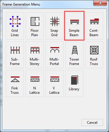
For more information Click HERE
This tutorial describes some of the basic techniques used in MasterFrame. Please take a few minutes to familiarise yourself with the various frame viewing tools; editing and data input methods and find how you can use the modify geometry area to select members.
Defining Member Section Properties
The Member Section Properties is now displayed. This allows you to set section properties to the beam.
Place the beam in front view by
selecting the Front side of the viewing
cube(  ).
).
Select Steel Sections from the bottom left-hand corner and from the section sizes drop list, select a 457x152 UB 52, grade S275.
The section size will have been applied to the simple beam.

Close the Member Section Properties dialogue by clicking on the X.
Editing the Geometry
You can now use the Modify Geometry options to modify the frame geometry
From the top toolbar turn on the member Lengths ( ) in the Members group to see the actual length of our beam.
From the Modify
Geometry menu and Change Coordinate Tools,
select the Shift XYZ option.


Turn on Node Dots from the Display section and set them to Medium.
Select the beam’s right endpoint. A orange dot
will appear, and the node number will be listed in the Move these nodes list
to confirm the selection.
Therefore we would like to shorten the beam from 9 m to 6 m, enter -3 in the X box under the And also apply a shift in tab.

Select Apply to carry out the shift.
Close the Shift XYZ dialogue by clicking on the X.
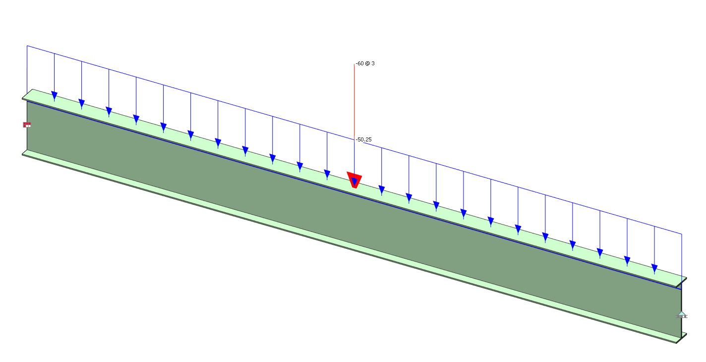
Applying Member Loading
To apply loading to a member, select Member Loading from the Loads menu.
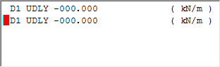
Click on the UDLY(  ) button (bottom left of the screen) twice
to add two uniform distributed load definitions.
) button (bottom left of the screen) twice
to add two uniform distributed load definitions.
The list of loads edit box now has two loads in it. Both loads are D1 UDLY -000.000 which means both assigned to the D1 dead load group, both of them uniform distributed load in the Y-Axis and acting downward.

We now need to edit these loads.
Pick the upper of the two loads to set the cursor focus to it and change the load to D1 UDLY -015.000 (kN/m) by overtyping the - 000.000 value.
Next, pick the second load or move your cursor along to it and change the load to L1 UDLY -020.000 (kN/m) by overtyping D1 with L1 to assign the load to the L1 live load group and overtyping - 000.000 value with -020.000.
Click on the PY button to add a point load definition. Pick
the point load in the list of loads edit box and change the load to(  ) L1 PY
-040.000 3.000 (kN, m).
) L1 PY
-040.000 3.000 (kN, m).
Close the Member Loads dialogue by clicking on the X.
Nodal Supports
The Single Beam wizard already defined a Pinned (dX, dY, dZ) with a ϕX restraint nodal support on the left-hand endpoint of the beam (node 1) and a y(dY) direction only restraint on the right-hand endpoint of the beam (node 2).
In this tutorial, we will not change the support condition, but introduce the nodal information area, and how to view the support conditions.
From the Restraints file menu, select Nodal Static Supports.

Using the dropdown list we can change between the created support conditions. List of nodes edit box shows the number of the nodes where the selected support is applied. Each support is graphically represented on the structural model.
Close the dialogue by clicking on
the Close (  ) button.
Load Cases
Design Code
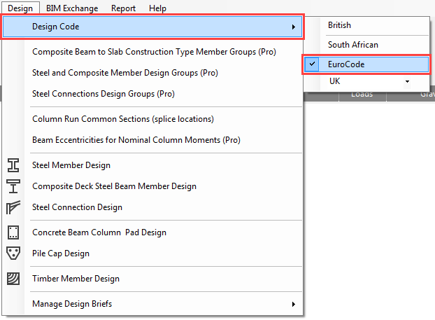
We need to make sure we are designing to Eurocode.
On the top menu, go to Design > Design Code and
check the selected code which should be Eurocode. If not, please select
it. If you are asked “Do you wish to change the Loading Cases in accordance
with the design code change” select Yes.
Go again to the Design > Design Code and check the national annex which should be the UK. If not, please select it. If you are asked “Do you wish to change the Loading Cases in accordance with the design code change” select Yes.
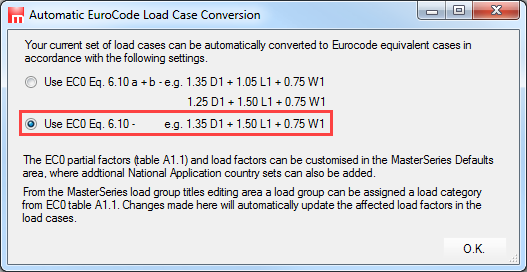
If you are asked which EC0 Eq. 6.10 set to use, choose the lower option 6.10
Loading Cases
From the Loads menu, select Load Cases.
By default, there are already two (or three in case of using EC0 Eq. 6.10 a+b by default) combinations of actions and case titles generated.
· Load Case 001: Dead plus Live (Ultimate) (Permanent Plus Variable)
· Load Case 002: Live Only (Serviceability) (Variable Only)
In this tab, we have the facilities to manage loading cases and define titles for them. However, for this example, we will retain the default loading cases and titles.

Density for Self-Weight
Self-weight of structural members is automatically included as a default set up.
The values for self-weight can be checked by going to Loads > Density for Self-Weight. To ensure that the self-weight is included, make sure the Include Member Density for Self-Weight checkbox is ticked. The default load group of the self-weight is the D1 but using the dropdown menu we can modify it.

Analysing the beam
From the top menu select Analysis, then Static Analysis.
The file will be saved automatically, and the
Analysis Type and License toolbar will now appear

Select Plane Frame and the frame will be analysed.
Viewing Graphic Results
From the Results file menu select Graphical Analysis Results.
Place the beam in front view by selecting the
Front side of the viewing cube( ) and turn off the 3D, if it is on.
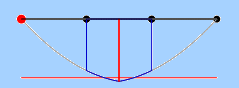
Select Bending Moment. We have no bending about the Minor axis so select Major Axis Only on the right-hand panel.
Select Show Values.
Change the B.M. scale to 200.

Using the drop list, at the bottom of the screen, we can select and view each of the Load Cases including the envelopes.
![]() Printing Graphic
Results
Printing Graphic
Results
Select the Print(  )button.
The Job Reference form enables you to finalise the job details on your printout just before printing them.
The Job Reference text boxes enable you to edit the job reference details that will appear in the printout.
While viewing the preview you can use all the tools on the top toolbar and the side menu, including zooming, panning, scaling and font sizes.
You can change the printer from the dropdown list of printers and alter the page orientation from portrait to landscape.

Select the Printer ( ) button.
Close the Job Reference dialogue by clicking on the X.
Select the Close button to exit the Graphical Analysis Output window.
Viewing Text Results
From the Results file menu select Tabular Analysis Results. This will take you into the Nodal Deflections table.
The options in the lower part of the screen
enable you to control the results being displayed and are very easy to use.
When there is a large amount of data the vertical scroll bar controls the view.
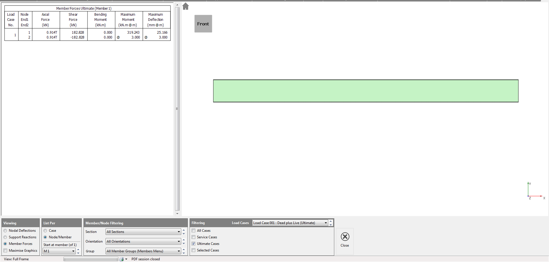
The standard method of viewing results is List per Case. This only display results in one loading case at a time. The other method is to List per Node/Member. This is useful to compare results for different loading cases for the same node or member as shown here.
Experiment with the various options to display the results.
To close Tabular
Analysis Results, select the Close( ) button.
Steel Design
Now we will design the steel beam.
From the Design file menu, select the Steel Member Design option.

In the case of a single simply supported beam, the program automatically applies an Axial with Moment design check to the member.
The results from this check are displayed in the main design output window. The cyan coloured background indicates that there is a design failure

The tabs at the bottom of the screen contain the information being used for the design check.
The Briefs and Section Sizes tab shows the section size and the loading case that is being used for the design. The program automatically detects design cases and serviceability cases. In this case there is only one of each.
Scroll down the design output screen using the scroll bar to the right of it. The results reveal that the beam is failing in both the moment capacity check and the lateral buckling check.
Select the Axial + Moment Design Data tab. In this tab, you may change fundamental design assumptions such as effective length, deflection limits etc. In most instances the default values are appropriate.
Select the Lateral Restraint - Minor Axis tab. In this tab, we can define position of lateral restraints along the length of the beam.
In Variable Portion Lengths - End 1 enter a value of 2.0.
The Variable Portion Lengths - End 1 entry is used as a shortcut for defining an equal spacing of lateral restraints over the entire length of the member. Entering values in further portions overwrites this assumption.
The Moment Capacity/Bending Moment diagram at the top of the design output window is now split up into three portions of equal length.
The design output relates to the currently
selected portion.
Click on the centre portion of the bending moment/capacity diagram to select the middle portion.
Go back to the Briefs and Section Sizes Tab.
Change the section list to list
by weight by selecting the Sort by Weight (  ) button when it has a border it is
on.
) button when it has a border it is
on.
Click on the Auto Size Current Member ( ) button.
The program will search for the lightest steel section of the current section type that passes all design checks.
Printing the Design Output
Select Print Design Output, from the Print menu.
The
print manager will appear at the bottom of the screen listing all the design
checks applied to the beam. The three portions of the design check are listed
separately since each portion has its own set of calculations.
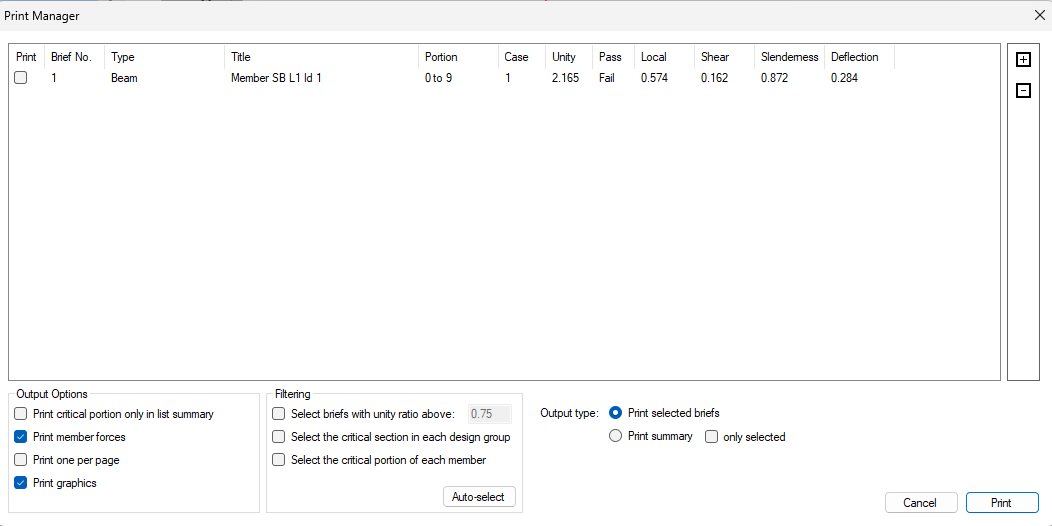
The output section gives the option to choose the output type. Check on Print member forces and print graphics. Check the Select the Critical Portion of each member from the filtering area.
This reduces the currently selected checks to the most critical portion in each member. In this case, only one check is highlighted.
There are two options available:
· Print Summary: print the list that is displayed in the print manager window
· Print Selected Checks: print full detail for the design output for the check highlighted in the list
The printed design output appears in the same format as shown on the screen.
Close the Steel design by clicking on the main X.
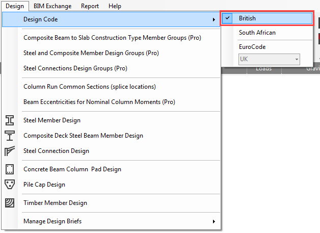
Redesigning for British Standards
The beam can be redesigned to another code at any stage.
On the
top menu, go to Design > Design Code
and change the selected code to British.
This will automatically change the loading combinations to British Standard. Now the beam can be re-analysed.
Select Static Analysis from the Analysis menu and analyse as a Plane Frame.
From the Design file menu, select the Steel Member Design option.
Change the section list to list by weight by
selecting the Sort by Weight ( ) button and click on the Auto Size Selected Member ( ) button.
This will automatically redesign the member to British Standard. The changes can be seen in the design output. Changes to the Maximum Moment and Deflection, and changes from Plastic to Class 1.
For Further Information Click 📑 Methodology
End of Tutorial
