MasterFrame Introduction
Version Information
These tutorials have been written for version 2025 of the MasterSeries software suite. Subsequent versions of the software may have additional features, or changes in layout, however the general procedure will remain the same.
Contact
We strive to make our tutorials as simple as possible without compromising on the technical aspects of the analysis procedure. Should you discover any errors, omissions, or are in need of additional clarification, please contact us by emailing your comments, or corrections to help@masterseries.com.
If you do not have access to any of this software, please contact us for a 14-day free trial to learn how it can benefit you and your business.
We’re social – follow us on Facebook, LinkedIn and Vimeo to keep up to date!
The Top Toolbar
The top toolbar in MasterFrame gives you access to numerous tools that you will find beneficial when examining and navigating through your model. This toolbar is dynamic in that it compresses and expands depending on the size of your computer screen. As it compresses the icons become smaller and their descriptions are no longer visible.
The full toolbar shows larger icons with their descriptions and, if required, the option to click on an arrow to expand the options available.
For More information Click HERE

The Actions toolbar
You can Save the MasterFrame file you are currently working on. This will save the current version of the file to the pathname shown at the top of the MasterFrame screen.
There is also the option to Undo or Redo the previous number of actions that were applied to the frame. The graphics will update each time to show the changes.
The Members toolbar
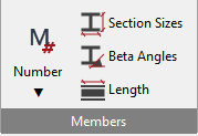
The member Section Sizes, Beta Angles (orientation), Lengths, member numbers (Number) and reference stamps (Show references) can be easily displayed on the members of the frame
The Nodes and Coordinates toolbar
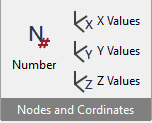
The node numbers (Number) and X, Y, Z coordinates (X Values; Y Values; Z Values) can be displayed for all the nodes in the current view of the frame.
The Supports and Restraints toolbar
You can display the frame nodal static supports (Support); any nodal spring supports that may have been added to the frame along with column settlements.
Member end releases can also be made visible (Releases).
If stiff deck diaphragm action has been applied to the frame, the surfaces that this has been applied to can be displayed (Stiff Deck).
The 3D Drawing toolbar
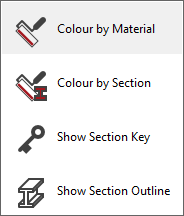
The elements in the frame can be shown graphically in 3D giving a ‘real’ view of the structure. The frame elements can be Coloured by material, for example, steel elements are shown in green, composite members in yellow, bracing members in blue, timber in brown and concrete in grey.
To further distinguish between section sizes, you can select to Colour by Section and then Show the section key which will give a legend displaying the section sizes and their related colours used on the frame.
Show Section Outline adds lines at the edges of the sections to enhance their outline.
The Draw Short option pulls the structural elements back from the nodes so you can see where an element starts and finishes and the extent of its continuity.
The Loads toolbar
See Adding the Loads section below.
Nodal Supports
Turn off all options so you have a simple wire frame with no values.
From the Restraints file menu, select Nodal Static Supports.
Nodes 1 to 5 are already defined as either Pinned or Fixed Supports depending on your choice at startup time.
Each support is graphically represented as
follows:
 Horizontal roller (dy restraint only)
 Pinned support (dx, dy, and dz restraints)
 Fixed
support (dx, dy, dz, fx, fy and fz restraints)
Fixed
support (dx, dy, dz, fx, fy and fz restraints)
Other support conditions are graphically represented as a set of 6 restraint boxes that are either active (red) or inactive (white). These 6 boxes represent the 6 degrees of freedom of the support. The order of the boxes is the directional restraints dx, dy, and dz followed by the rotational restraints fx, fy and fz.
For example:
 Other support (Top line
directional dy, bottom line rotational fx and fz active)
Other support (Top line
directional dy, bottom line rotational fx and fz active)
Adding Section Sizes
As we did not define the section sizes during the multi-storey frame generation processor, now we must add some preliminary section sizes to the frame.
From the Properties file menu, select Member Sections Materials.
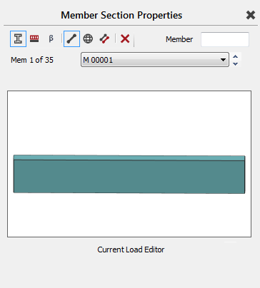
In the Member Section Properties, there are 2 sets of 3 options.
The first 3 options (#1) are the Attributes a member can have.
 The Section
Properties, e.g. steel, concrete or timber and section size.
The Section
Properties, e.g. steel, concrete or timber and section size.
 The
Member Loading applied, e.g. uniform,
point, trapezoidal etc.
The
Member Loading applied, e.g. uniform,
point, trapezoidal etc.
 The
Member Orientation b (rotation) of the member.
The
Member Orientation b (rotation) of the member.
The second 3 options (#2) represent the method of editing as follows:
 Edit
Member mode: Applies all changes to
the currently selected member (highlighted). This is instantaneous.
Edit
Member mode: Applies all changes to
the currently selected member (highlighted). This is instantaneous.
 Edit
Global mode: Applies all changes to a
group of members (shown in red). This is a global search and replace function,
e.g. change all members that have a 457x152x52UB to a 457x191x67UB. This is
instantaneous.
Edit
Global mode: Applies all changes to a
group of members (shown in red). This is a global search and replace function,
e.g. change all members that have a 457x152x52UB to a 457x191x67UB. This is
instantaneous.
 Edit and Paste (Copy to):- This option enables you to edit a
template and then apply it to any member by clicking on that member in the
graphics area. No changes are made until you select a member.
Edit and Paste (Copy to):- This option enables you to edit a
template and then apply it to any member by clicking on that member in the
graphics area. No changes are made until you select a member.
 Remove
all selection sizes: This
“additional” option enables you to delete all section sizes or b angles on all members.
Remove
all selection sizes: This
“additional” option enables you to delete all section sizes or b angles on all members.