Response Factors of Steel Staircases in MasterSeries
MasterSeries can be used effectively for the global analysis, design, and vibration assessment of steel staircases, but there are important modelling considerations and limitations that users must understand at the outset. There is no dedicated staircase template within the software, and staircases must be modelled explicitly using either line elements, FE surfaces, or a hybrid approach, depending on the level of accuracy required.
It's important to note that the engineers goal should be to model the stiffness of the strain as accurately as possible. Assuming a less stiff model may seem conservative, however in vibration design response factor assessment design is driven by the interaction between the natural frequencies developed and the harmonics of the walking activity. By making the structure less or more stiff than it actually is, this interaction could offset and the realistic response of the structure to the activity is not captured, perhaps missing critical resonant responses.
1. General Modelling Capabilities and Limitations
No curved or double-curvature members can be modelled directly in MasterFrame.
Spiral or helical stairs must therefore be represented using a faceted approximation (multiple straight segments).
There is no automatic stair generator for straight, dog-leg, or spiral stairs.
Weld behaviour and local connection flexibility cannot be modelled explicitly.
Staircases are inherently sensitive to modelling assumptions, particularly for vibration assessment.
As a result, engineering judgement is essential, and results should always be validated against simplified hand checks or published guidance.
2. Typical Modelling Approaches
A. Wireframe (Line Element) Modelling
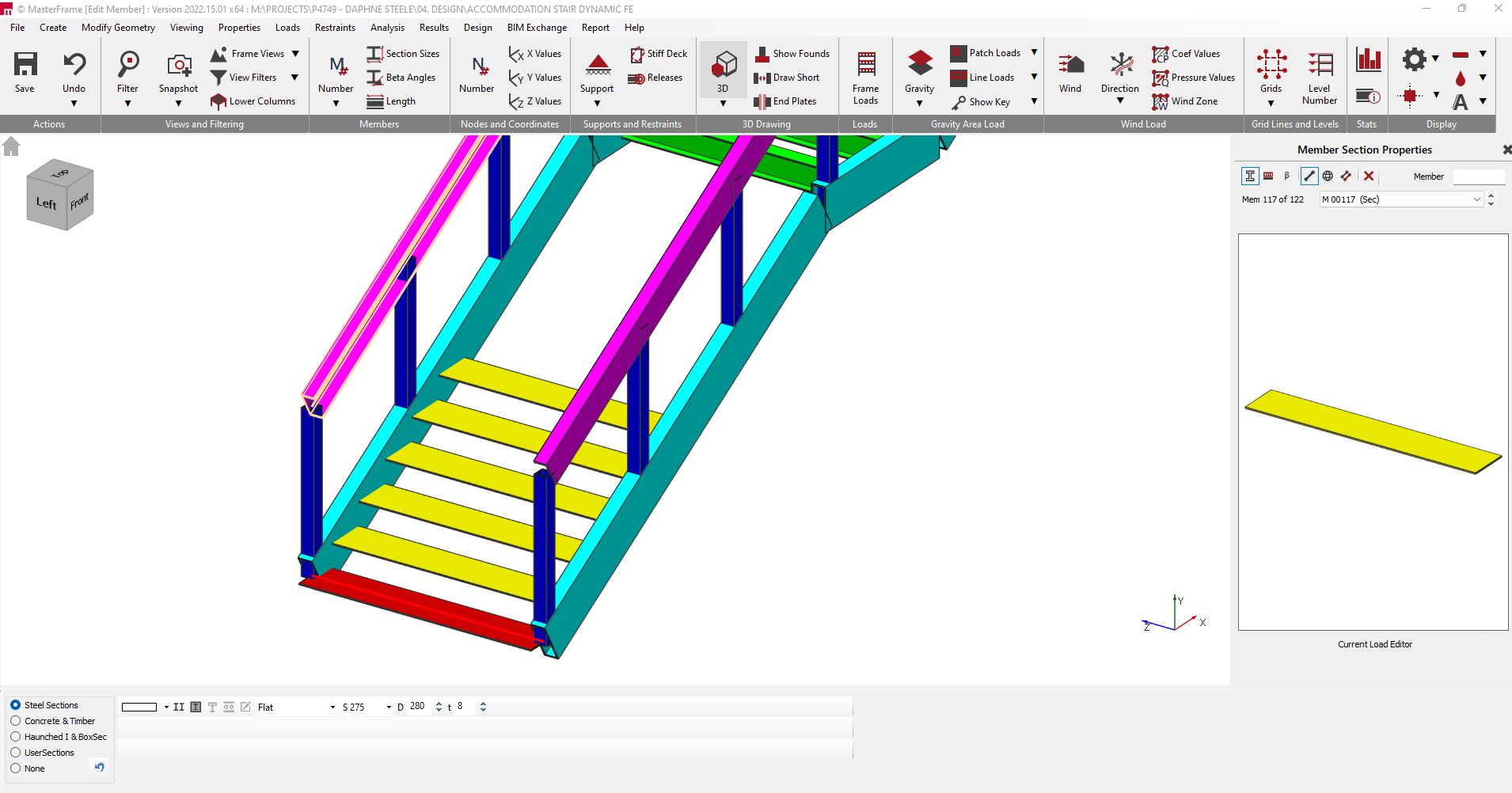
Stringers, beams, and landings are modelled as line elements.
Suitable for:
Global strength checks
Preliminary vibration screening
Simpler stair arrangements,, e.g. open risers
Limitations:
Poor representation of plate action in treads and landings
Where there is a closed or partial closed riser, i.e. a vertical plate beneath the tread, it becomes more difficult to model this behaviour with simple line elements
Where riser is fully closed and the treads are then connected, the system then acts a complete assemblage, and simple line elements are no longer appropriate.
Simplified stiffness connection between treads and stingers
Can under- or over-estimate stiffness for vibration checks
Since response factor is only evaluated at nodes, one or more internal nodes are required in the length of treads. Additional tread nodes also capture more accurate local tread natural frequencies.
This approach is often sufficient where vibration performance is not critical or where conservative assumptions are acceptable.
See also: 📄 Designing Flat Plate Stair Stringers to Eurocode 3 in MasterSeries
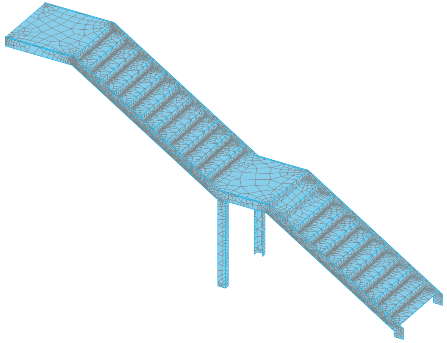
B. FE Surface Modelling (Plates)
FE modelling is possible and often preferred for dynamic analysis and architecturally sensitive stairs.
Treads, risers, and landings are modelled as 2D FE surfaces.
Each FE surface must be defined by closed boundary members (dummy line elements).
Suitable for:
Human-induced vibration analysis
Plate bending behaviour of steel treads and landings
Feature or cantilevered stairs
Limitations and cautions:
Considerably more modelling effort
Meshing can be difficult, especially:
Near stringers
At tread–riser junctions
Where nodes lie close to boundaries
Geometry may need to be simplified to achieve a valid mesh, e.g. small geometric distance in the tread/riser interface with the stringer.
Results remain an approximation of real behaviour
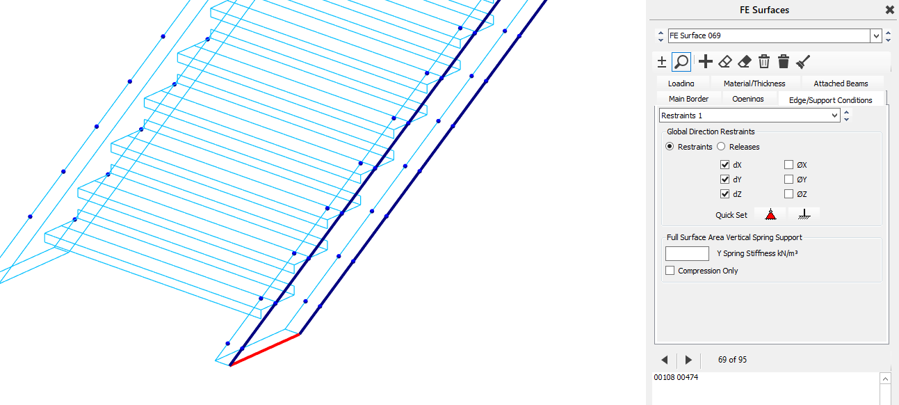
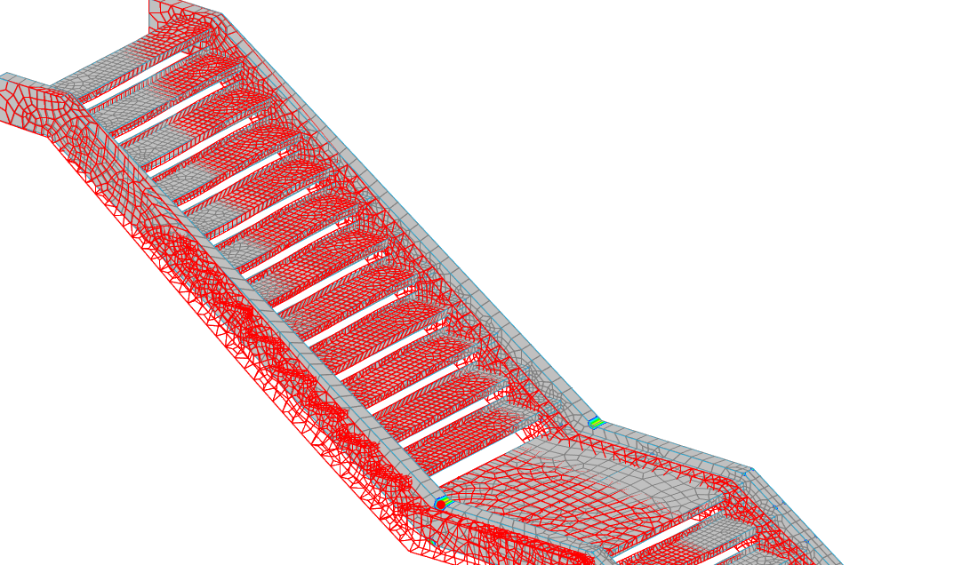
A common and practical solution is to combine line elements and FE surfaces:
3. Dynamic and Vibration Analysis of Steel Stairs
The outlines the procedure for modelling and analysing steel or concrete staircases for vibration in MasterSeries, utilizing Finite Element (FE) surfaces for the stair flights and attached beams for landings.
Modelling the Structure
To accurately capture the stiffness and mass distribution, the staircase should be modelled using MasterFrame and the FE surfaces module.
- Stair Flights (Stringers and Treads): Model the stringers as vertical FE surfaces (plates or channels) and the treads/risers as inclined/horizontal FE surfaces. This ensures continuity and avoids geometric alignment issues associated with using 1D attached beams on sloping elements. Ensure the mesh nodes connect the stringer surfaces to the tread surfaces to ensure composite action.
- Landings: Landings can be modelled as horizontal FE surfaces. Supporting members under the landing can be modelled as 1D Line Elements set to "Attached Beams". Ensure "Beam-Plate Offset" is selected (typically "Bottom") to correctly locate the beam stiffness relative to the slab centroid.
Modal Analysis (Natural Frequencies)
Before calculating response factors, perform a natural frequency analysis to determine the stair's dynamic characteristics.
- Mass Loads: In the Edit Mass Load Contribution area, select the static load groups to convert to dynamic mass. This typically includes 100% of Dead Load (Self-weight + superimposed) and a portion of Live Load (often 10% or a factor of 0.1).
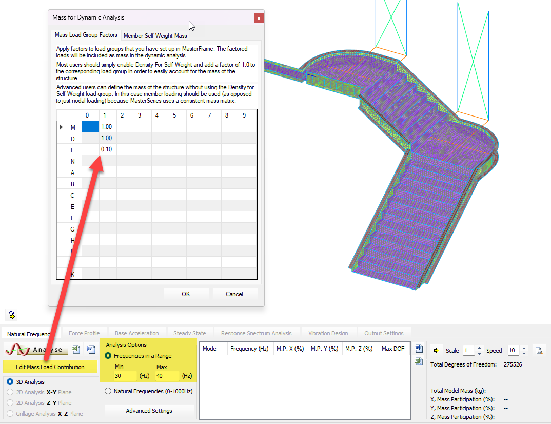
- Frequency Range: Staircases are stiffer than floors and often have higher fundamental frequencies. Set the analysis range to calculate frequencies up to at least 30 Hz or 40 Hz (higher than the default for floors) to capture relevant harmonics.
- Mass Participation: Review the results for modes with significant Mass Participation in Y (vertical direction) to identify the critical modes for the stair flight.
Vibration Design Setup
Navigate to the Vibration Design tab to calculate Response Factors.
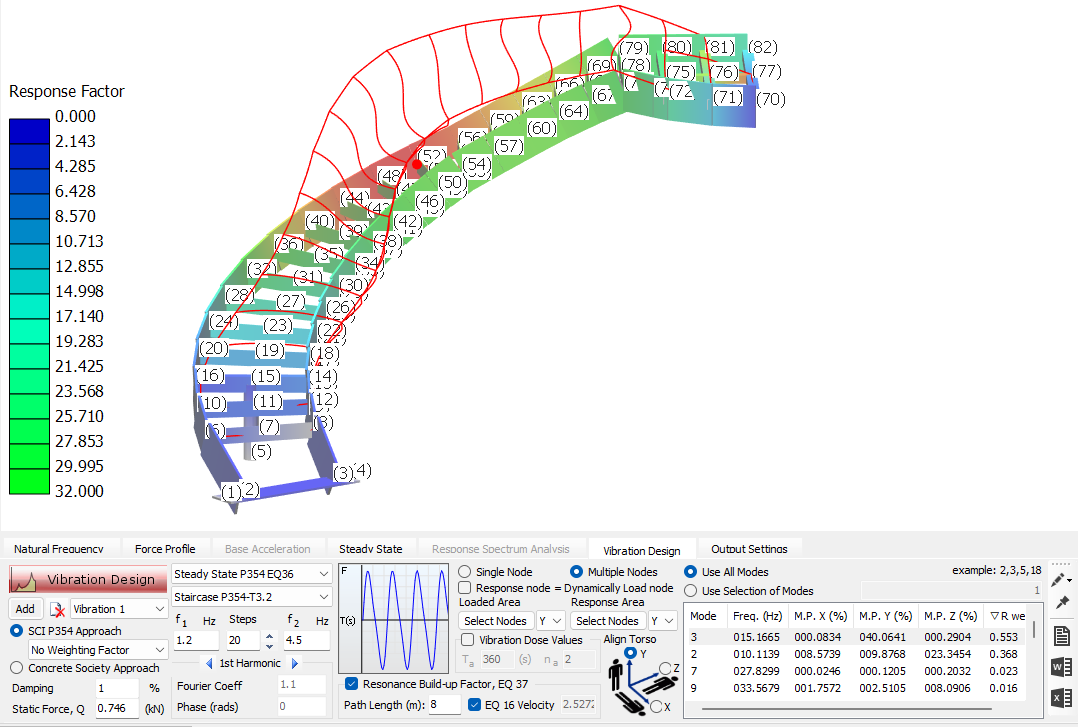
- Code & Function: Select the design code (e.g. SCI P354). Set the Forcing Function to Staircase. This adjusts the Fourier coefficients used in the calculation.
- Frequency Range: Set the walking frequency range from 1.2 Hz to 4.5 Hz. This is wider than the range for floors to account for rapid descent.
- Analysis Type: Select Steady State. Although stairs are high-frequency structures, industry guidance (such as SCI AD 406) advises against using Transient analysis for standard staircases. The contact time of a footstep on a stair is often long compared to the natural period, causing destructive interference that Transient analysis may not correctly capture.
- Damping: Enter a damping ratio appropriate for the stair finish (e.g., 0.5% for bare steel, increasing for filled pans or carpeted finishes).
Result Refinement
Key considerations:
FE surface modelling generally provides a better stiffness representation for vibration response than wireframe models.
Connections may be assumed fixed for dynamic analysis, as vibration amplitudes are small and friction is not overcome.
For the Mode Shape Analysis (Natural Frequency calculation) of steel and concrete staircases, it is recommended to calculate frequencies in the range of 0 Hz to 30 Hz or 40 Hz. Although standard walking frequencies generally range between 1.5 Hz and 2.5 Hz, staircases are subject to higher pacing frequencies, potentially up to 4.5 Hz. The 30–40 Hz range is selected to ensure the analysis captures the relevant mode shapes up to the fourth harmonic of these pacing frequencies, ensuring the structural response is adequately captured.
Regarding the necessity of Steady-State versus Transient analysis, the standard guidance in SCI P354 defines a "Low Frequency" cut-off of 12 Hz for staircases. Typically, if the fundamental frequency is below this limit, both Steady-State and Transient analyses are required, whereas if it exceeds the limit, usually only the Transient analysis is checked.
However, SCI Advisory Desk Note 406 provides critical, updated advice specifically for staircases. It recommends that for orthodox staircases, which typically have natural frequencies greater than 15 Hz, the Transient response should not be considered. This is because the assumption of "instantaneous impulsive loading" used in transient calculations is invalid when the structural frequency is high relative to the contact time of a footstep. Furthermore, for staircases with frequencies below 15 Hz, achieving Steady-State criteria is often difficult; in such cases, it is often appropriate to utilize Vibration Dose Values (VDV) or Resonance Build-up Factors to account for the intermittent nature and short duration of staircase usage.
Staircases often yield high Response Factors (e.g., R > 30) under standard steady-state analysis. If results exceed limits, apply the following modifiers allowed by SCI P354:
- Vibration Dose Values (VDV): Use this to account for intermittent usage. Define the number of uses per day (e.g., 20 times) and duration (e.g., 16-hour day). This significantly helps qualify stairs that are not subject to continuous traffic.
- Resonance Build-up Factor: Enable this factor and input the Path Length (e.g., the length of the flight, approx. 3-5m). This reduces the response factor by accounting for the fact that a user traverses the stair before full resonant vibration can build up.
Damping Values
The SCI P354 guide provides standard values for use in design unless more accurate information is available, which includes 0.5% for fully welded steel structures, such as staircases.
Always review results against SCI P354 and exercise caution when interpreting response factors.
4. Meshing and Stability Considerations
Poorly shaped FE elements (near-triangular) will cause instability or analysis failure.
Small geometric gaps can force excessively fine meshes.
Practical tips:
Add small dummy members to guide mesh topology
Avoid unnecessary upstands or small geometric detail
Run a static analysis first to verify restraints and mesh quality before dynamic analysis
Expect different PCs to mesh large FE models slightly differently at very small element sizes
High local stresses generally do not significantly affect the global dynamic analysis. For example high local stresses at a connection point (often called singularities) are usually artifacts of the finite element mesh density at a point load or restraint. While these stresses are critical for static structural design, they do not inherently change the global stiffness or mass of the stair system enough to alter the fundamental frequency or mode shapes.
5. Spiral and Feature Staircases
Spiral stairs require faceted approximations in plan and elevation.
FE surfaces must remain planar.
Case studies demonstrate feasibility, but these models are advanced and should be treated with care.
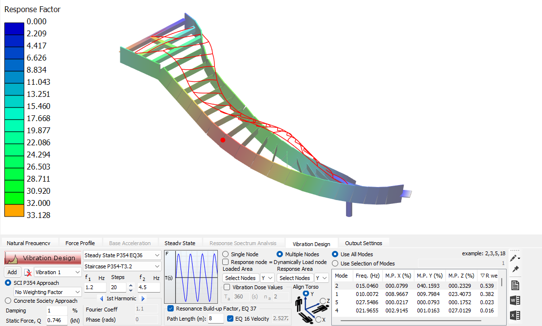
Reference example:
Feature staircases | London, UK
6. Validation and Good Practice
There is no single “correct” modelling approach for steel stairs.
Always:
Start simple and add complexity gradually
Check global equilibrium and deflections
Compare against hand calculations or published guidance
Treat vibration results as indicative, not absolute
For vibration design, refer to:
SCI P354
Steel Designers’ Manual (7th Edition), dynamic analysis chapters
Summary
MasterSeries can be used successfully for steel staircase analysis and vibration assessment, but staircases sit at the edge of conventional structural modelling. Accurate results depend far more on modelling judgement, simplification, and validation than on software settings alone.