Steel Connection Design Groups - Integration and Brief Management
Connection design groups are a powerful feature, especially in integrated mode, to streamline your design process.
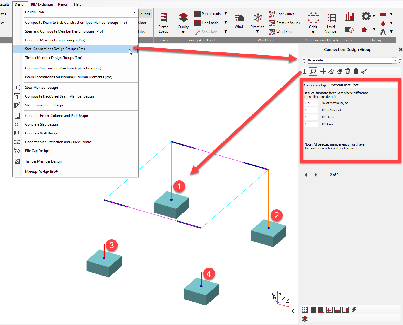
- Grouping Similar Connections: You can group together nodes or members that require the same connection layout. For instance, you might group all similar rafters or base plates into a single design group.
- Optimised Design: When a design group is created, the software will examine the forces and moments from all load cases for all members within that group. It then produces an optimum solution that satisfies all design criteria for every member in that group. This means you design one connection, and it is automatically applied and checked against all relevant scenarios for the entire group.
- Efficiency: This significantly speeds up the design process as you don't have to design each individual connection separately, even if they have slightly different load cases or deflections due to various frame actions (e.g., sway).
- Visual Indication: In the software, a small green symbol is used to indicate that a joint is part of a connection design group, highlighting that you are designing not just one joint but multiple matching connections simultaneously.
Connection Referencing
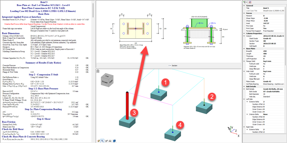
In MasterKey: Moment and Simple Connections, each specific design for a member is referred to as a design brief. Multiple design briefs can be stored within a single data file. When a connection design is applied to a joint in a linked Masterframe model, it can be assigned manually by selecting the required joint type and then the member. You have the ability to edit the title of any given brief.
Integrated Links to Masterframe
The MasterKey: Moment and Simple Connections module offers deep integration with Masterframe models.
- Automatic Data Import: When you link a connection design to a Masterframe model, the connection geometry and forces are automatically imported from the Masterframe analysis results. This eliminates the need for double modelling and significantly reduces the risk of manual errors.
- One-Way Link: The design link is generally a one-way connection. This means any changes made in the Masterframe model (such as loads, sections, or load cases) will automatically update in the connection module when it's accessed. However, if you make modifications to section sizes or connection forces directly within the connection module, these changes will not be reflected back in the Masterframe model. The original Masterframe data will be re-loaded if the connection brief is refreshed. To permanently change geometry or forces, you must exit the connection module, make the changes in Masterframe, and then re-analyse the model.
- Experimentation: The ability to temporarily modify forces and sections in the connection module is intended for experimentation to determine the required connection geometry before implementing changes in Masterframe.
Colours of Different Member Ends
When viewing your Masterframe model within the connection module's display pane:
- Members shown in cyan indicate that no connection design is currently associated with that particular member.
- Members displayed in black, along with a black dot at the end, signify that a connection design is associated with that member end.
Selecting the Correct Connection Type
MasterSeries uses specific templates that correspond to defined physical geometries (e.g., "Beam to Column Flange", "Apex", "Base Plate").
Template Library: The software provides a library of templates (Moment, Simple, Bracing). Selecting the closest match reduces the amount of manual editing required.

Selecting the Correct Member End
When you select a member in the connection design module, the software imports the forces (Moment, Shear, Axial) specifically from that node.
Specific Examples:
- Eaves: Select the lower end of the rafter.
- Apex: Select the upper end of the rafter.
- Base Plates: Select the bottom end of the column.

Importance of Selecting the Right Element/Member End
Selecting the correct element or member end is crucial because it directs the software to the specific joint you intend to design. In an integrated design mode, once you select a member, the software automatically retrieves its section size, forces, and other relevant geometry from the Masterframe model for that specific joint. Different connection types are designed for specific member orientations and joint configurations (e.g., beam-to-beam, beam-to-column, bracing connections). The system will then present the appropriate design options and checks based on that initial selection. For example, picking a beam connected to a column will automatically set up an "eaves" connection, while picking a beam supported by another beam will lead to a "beam-to-beam flexible end plate" connection, each with its own specific input parameters and design considerations.
Design Groups: Correctly selecting the member end allows the software to automatically identify geometrically identical connections elsewhere in the frame. It then groups them, ensuring the design covers the worst-case loading from all valid members in that group.
How to Visually Review/Check for Loads
In the integrated connections design module, reviewing and checking loads is integrated into the workflow:
- Automatic Load Import: For moment connections, all ultimate limit state load cases from your Masterframe analysis are automatically imported into the connection design module. For simple connections, the software automatically identifies and uses the maximum shear force from the analysis results.
- Load Case Selection: You can then select the desired load case from a dropdown menu within the property grid to view its specific design calculations.
- Dynamic Calculation Display: The design calculations are updated dynamically as you change inputs or select different load cases. The results area displays calculations in four columns: Description, Design data, Calculation results/permissible values, and Design check results/clause notes (indicating 'OK' or 'Warning').
- Visual Failure Indication: If any design check fails, the calculation pane's background will turn cyan, and a warning note will appear, indicating the failing checks. Critically, failures are also indicated graphically on the connection display with small red symbols. For example, a failing bolt row in tension might be indicated by a red square.
- Scan for Brief Failures: It is advised to use the "scan for failures" function. This feature will run through all ultimate limit state load cases to ensure that the connection is satisfactory, stopping at the first failing brief if any issues are found. This is important because the most onerous load case might not be immediately obvious just by looking at utilisation ratios.
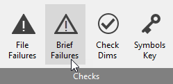
- Dimensional Checks: The software also performs detailing rules and dimensional checks, turning the graphical area's background to cyan if there are any detailing issues and providing a detailed description of the problems in the "Check Dims" screen. This helps ensure constructability, such as preventing bolt clashes.
Unlinking Integrated Connections
See example below:

For Brief 2 apex connection, this has become unlinked from the member end and is operating as a standalone connection (having retained perhaps some information forma previous link). The drop list of loads cases has only one case.
For Brief 3 apex connection it is linked to the wrong end of the analytical member near the apex.
The fix for both is it relink the connection using the 'Apply mode' which you are likely familiar with. Select brief , go into apply mode, then click at the analytical member end near the apex to establish/correct the link. Make sure to go back to 'Find Mode' (binoculars to right of apply) after this to avoid unintentionally applying the brief to other member ends.
Corrected.

You can also see from the drop list of load case in Brief 2 has now been populated.
