T01-2 MasterFrame Tutorial
2D Simple Steel Frame Design to Eurocode 3
📑 Introduction to MasterFrame

Introduction
MasterFrame is a piece of advanced structural frame analysis software that allows you to analyse everything to beams, and trusses to multi-storey frames and complex 3D models in any type of material.
MasterKey Steel Design allows for the design of members in steel structures analysed using MasterFrame, or MasterPort to the BS, Euro or SABS codes.
If you do not have access to any of this software, please contact (Support) us for a 14-day free trial to learn how it can benefit you and your business.
Overview & Outcome
This tutorial gives you a quick tour of MasterFrame, introducing you to the most important concepts and features along the way. You will create and analyse a steel frame, as shown in the following MasterSeries Printed Output.
In general, the basic steps involved in using MasterFrame are as follows:
1. Generate the frame geometry
2. Define member properties, orientation and loading
3. Define supports and nodal loading
4. Define loading cases and combinations
5. Analyse the frame
6. View results
7. Design and optimize your frame & re-analyse
8. Print Results
Version Information
This tutorial has been written for version 2024 of the MasterSeries software suite. Subsequent versions of the software may have additional features, or changes in layout, however the general procedure will remain the same.
Contact
We strive to make our tutorials as simple as possible without compromising on the technical aspects of the analysis procedure. Should you discover any errors, omissions, or are in need of additional clarification, please contact us by emailing your comments, or corrections to help@masterseries.com
We’re social – follow us on Facebook ,LinkedIn and Vimeo to keep up to date!
Loading MasterFrame
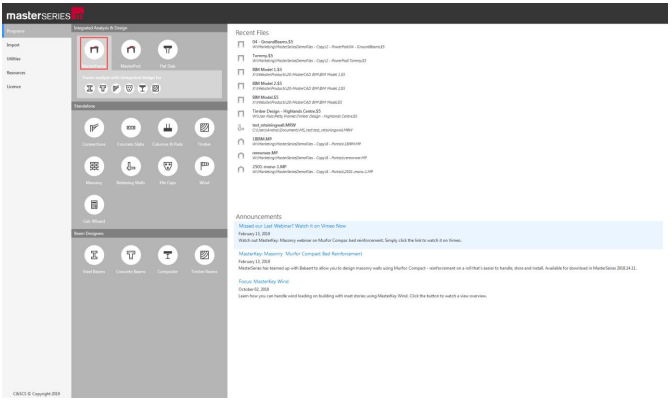
To start this tutorial, launch the main program of MasterSeries. While standing on the Programs tab, select the MasterFrame from the Integrated Analysis & Design filed.
The File Selector Dialogue
The File Selector dialogue will now be displayed. You can use the File Selector to navigate in your folder tree and to select, modify or delete your existing model files or create a new one.

The left side of the File Selector is a usual Windows file tree (#1) which can be used to navigate between the folders. By clicking with the right mouse button on one of the folders in the tree, the following functions will be available:
 ) button on the top of the file selector tree, we can see the saved
favourite folders. By selecting one of them, the file tree will immediately jump to there. By clicking the
Star icon at the end of the line, we can remove or add each of them.
The table, on the right of the File Selector (#3), lists all of the MasterFrame models contained in
the selected folder.
) button on the top of the file selector tree, we can see the saved
favourite folders. By selecting one of them, the file tree will immediately jump to there. By clicking the
Star icon at the end of the line, we can remove or add each of them.
The table, on the right of the File Selector (#3), lists all of the MasterFrame models contained in
the selected folder.The Frame Generation Menu
In most cases, you will be able to select a start-up frame and then tailor it to your specific requirements. In this case, we will create the members using the Snap Grid.
The Frame Generation Menu (Frame Wizard) is now displayed as shown. 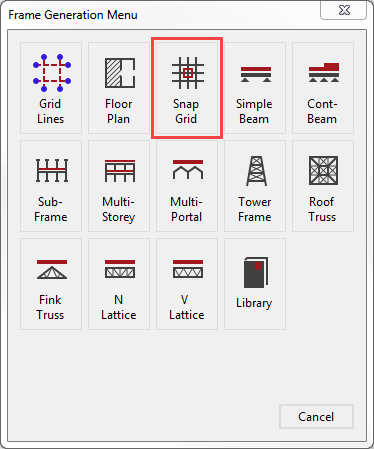
For more information Click 📑 Starting a new Frame
This tutorial describes some of the basic techniques used in MasterFrame. Please take a few minutes to familiarise yourself with the various frame viewing tools; editing and data input methods and find how you can use the modify geometry area to select members.
Creating the Members
Selecting the Snap Grid option, the Add Members (General) option is now activated and the snap grid visualisation is turned on.
Before we start creating the members, place the snap grid in
front view by selecting the Front side of
the viewing cube (. )
)
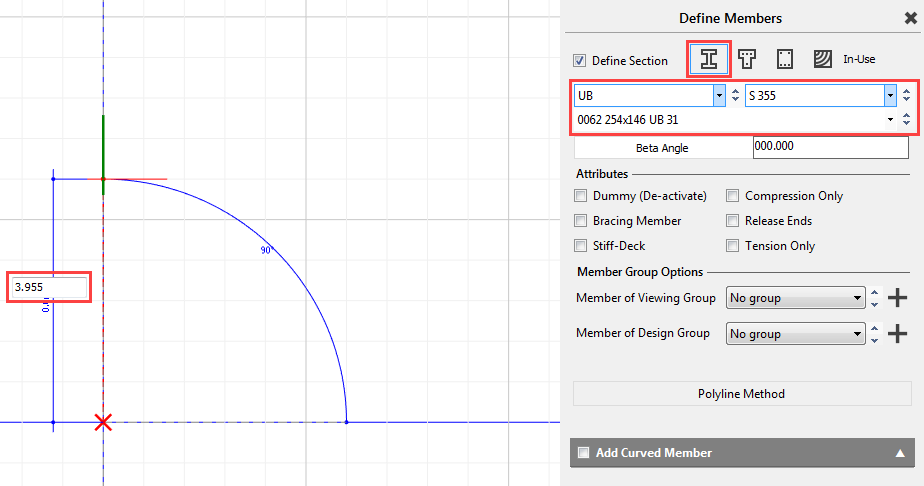
Choose Steel (  ) option and choose the 254x146 UB
31 of grade S 355.
) option and choose the 254x146 UB
31 of grade S 355.
Start drawing the first column’s bottom point by clicking on 0,0 point of the snap grid (intersection point of the blue gridlines). While we are moving, MasterFrame shows the actual length of the member. We will move vertically up. We can either snap up, or we can type in the exact member length.
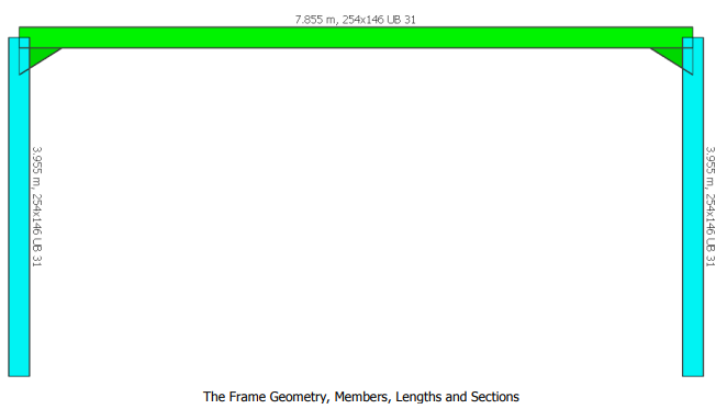
Let’s type in 3.955m using the keyboard and apply it by pressing the Enter button. Our first column is created.
We will then draw the other column by hovering the base point of the first column getting a red X on it. Now it is activated as a snap point. Move Horizontally to the right and type in 7.855m and press the Enter button to place the bottom point of our second column.
As we move vertically up, we will get with the intersection point with the other column’s height. Click on it to place the end point of our second column.
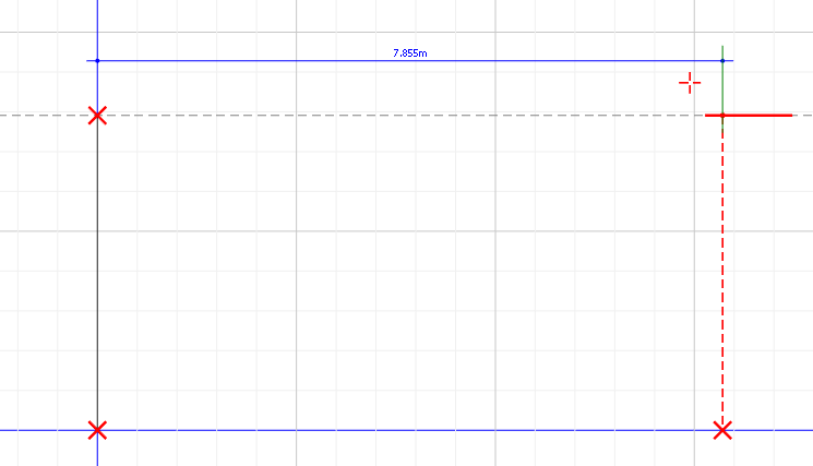
And then we will just join the column ends to create the beam member by clicking on the first column’s top point and then the second column’s top point.
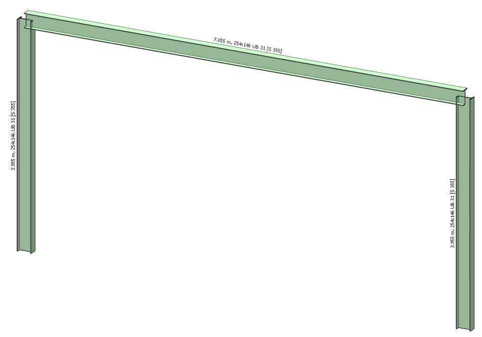
By selecting the 3D ( ) option from the top toolbar’s 3D Drawing group we
can see our frame in 3d.
) option from the top toolbar’s 3D Drawing group we
can see our frame in 3d.
Close the Define Members dialogue by clicking on the X.
Modifying Member Properties
We will modify our uniform beam into a hunched member.
From the Properties file menu, select Member Sections Materials.
To set the section properties to the current member, select Section Properties ( ) and Edit
Member (
) and Edit
Member ( ) mode.
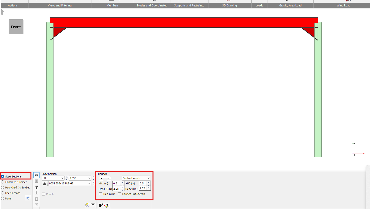
Select the beam member. Using the drop-down menu on the bottom dialogue, select the Double Haunched Member option.
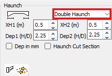
Set the XH1(m) and XH2(m) haunch lengths to 0.5m.
And then set the Dep1 (H/D) and Dep2 (H/D) haunch depths to 2.25 times of the serial depth of the original section.
We use a value greater than 2 as the haunch starts at the node point and by the time it is outside the column & end plate it will be less than 2.
Close the Member Section Properties dialogue with the X.
Chapter 3 MasterFrame - 3.4 – 3.6 The member Information Editing Area, Defining Member Materials and Section Properties, Member Orientation
Adding the Loads
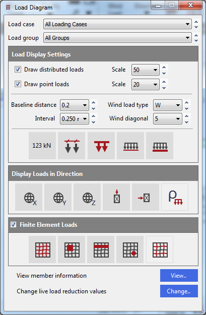
From the top toolbar select the Frame
Loads(  ) button to display the frame loading
on the graphical area and the Load Diagram control panel.
) button to display the frame loading
on the graphical area and the Load Diagram control panel.
Change the top drop list of Load Case to All Loading Cases to show all the applied loads with default values (without safety factors).
The frame Load Diagram controls are on a floating form. Click on the minimise button -, to hide it, but keep it active.
Applying Member loading
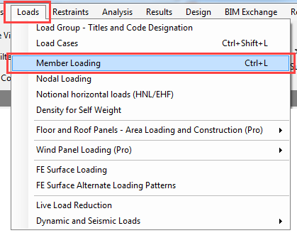
From the Loads file menu, select Member Loading.
In Edit Member ( ) mode and then select the beam member
again.
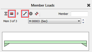
Click on the UDLY ( ) button (bottom left of the screen)
twice and once on the Point Load to add(
) button (bottom left of the screen)
twice and once on the Point Load to add(  )two uniform distributed load and a
point load definition.
)two uniform distributed load and a
point load definition.
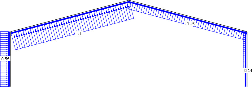
The list of loads edit box now has three loads in it. The two UDL loads are D1 UDLY -000.000 which means both assigned to the D1 dead load group, both uniform distributed load in the Y-Axis and acting downward. The point load is D1 PY -000.000 0.000 which means it is also assigned to the D1 dead load group, and it is a point load in the Y-Axis.
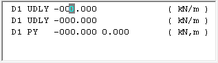
We now need to edit these loads.
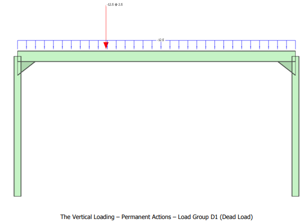
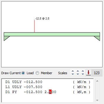
Pick the first UDL load to set the cursor focus to it and change the load to D1 UDLY -012.500 (kN/m) by overtyping the - 000.000 value.
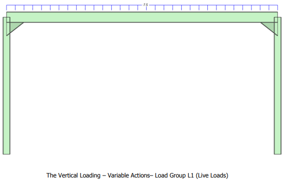
Next, pick the second UDL load or move your cursor along to it and change the load to L1 UDLY -007.500 (kN/m) by overtyping D1 with L1 to assign the load to the L1 live load group and overtyping -000.000 value with -007.500.
And finally, select the point load and change the load to D1 PY -012.500 2.500 (kN,m) by overtyping - 000.000 0.000 values with -012.500 2.500, which means the intensity of it is 12.5kN in the Y-Axis and acting downward and positioned 2.5m along the member.
Close the Member Loads dialogue with the X
Applying Nodal loadings
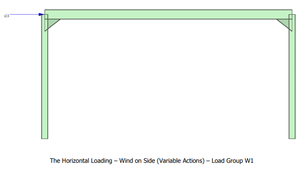
Wind loading will be simulated with a simple horizontal point load on the left eaves point. We will now use the Nodal Loading option for the practice.
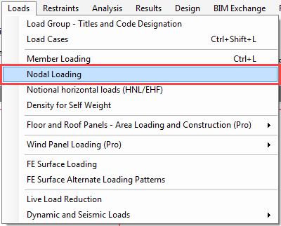
From the Loads file menu select Nodal Loading.
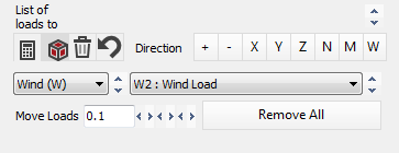
Pick the left eave point and set the FX to 12.5 kN.
Finally, change the Load Group setting to Wind (W), W1 : Wind Load.
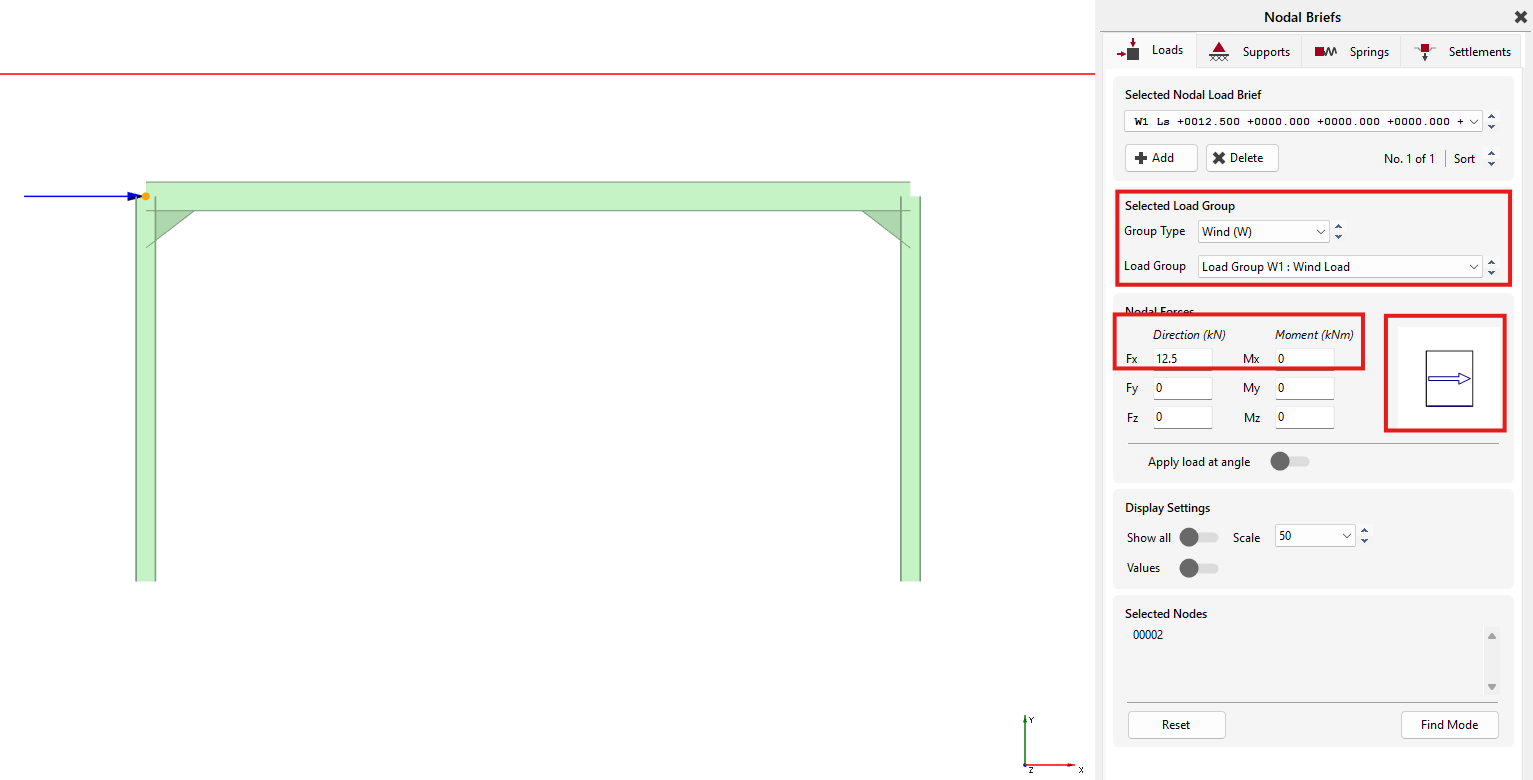
Close the Nodal Loading dialogue with the Close( ) button.
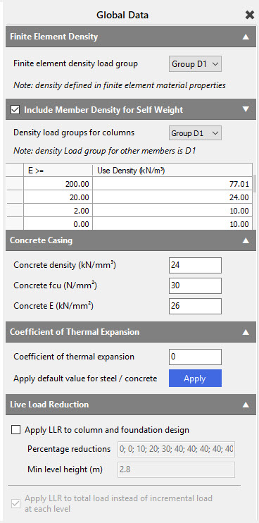
Applying Density (self-weight)
Self-weight of structural members is automatically included as a default set up.
The loadings due to
self-weight can be viewed in the frame Load Diagram,
by turning off all other loads except the Draw
Density Load (Self weight) ( ) button.
The values for self-weight can be checked by going to Loads > Density for Self-Weight. To ensure that the self-weight is included, make sure the Include Member Density for Self-Weight checkbox is ticked. The default load group of the self-weight is the D1 but using the drop-down menu we can modify it.
Loading Cases and Load Groups
Design Code We need to make sure we are designing to Eurocode.
On the top menu, go to Design > Design Code and check the selected code which should be Eurocode. If not, please select it.
If you are asked “Do you wish to change the Loading Cases in accordance with the design code change” select Yes.
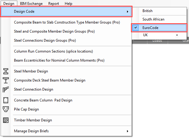
Go again to the Design > Design Code and check the national annex which should be the UK. If not, please select it.
If you are asked “Do you wish to change the Loading Cases in accordance with the design code change” select Yes.
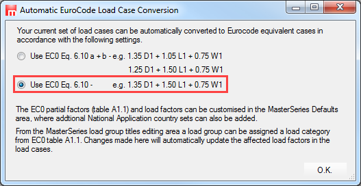
If you are asked which EC0 Eq. 6.10 set to use, choose the lower option 6.10.
Load Groups
Each action on the frame is assigned to a load group (e.g., Dead, Live, Wind, Notional etc.). MasterFrame allows 140 different load groups to be used; the most regularly used being groups D0 to D9, L0 to L9, W0 to W9 and N0 to N9.
A load group (e.g., D1) is a group of loads that are always applied together with the same load factor. These loads may be of different types (e.g., UDL, PY, and TY1) and have different values. However, since they are always applied together with a common load factor, they are in the one load group.
A
typical example of a load group is a wind load (blowing onto the side of a
building) that has different load intensities on each face of the building, but
are grouped into one group (e.g., W1)
In this tutorial, we use 3 load groups as follows:
- D1 - Permanent Actions (Dead Load)
- L1 - Variable Actions (Live Loads)
- W1 - Wind Load (Variable Actions)
Generate All Loading Cases
From the Loads file menu select Load Cases.
In MasterFrame you create and analyse Combinations of Actions. We do not create basic cases and then add them together post analysis. The reason for this is, if you form plastic hinges, do p-delta analysis or have tension or compression only members then you cannot use the “Superposition Principle” to add results from different basic cases together.
By default, there are already two (or three in case of using EC0 Eq. 6.10 a+b by default) combinations of actions and case titles generated.
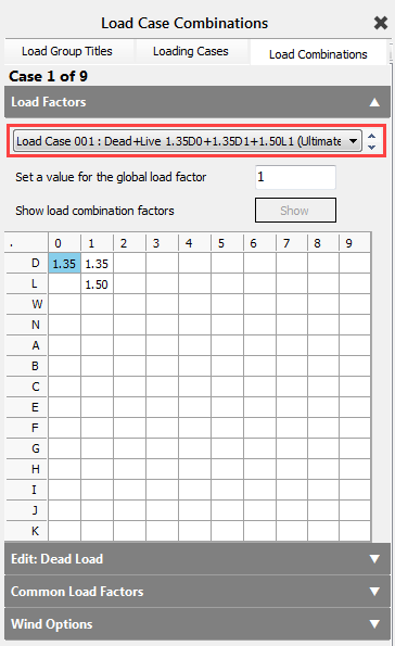
Load Case 001: Dead plus Live (Ultimate) (Permanent Plus Variable)
Load Case 002: Live Only (Serviceability) (Variable Only)
We will overwrite them using the Auto-Generate
Cases function to create all loading
cases.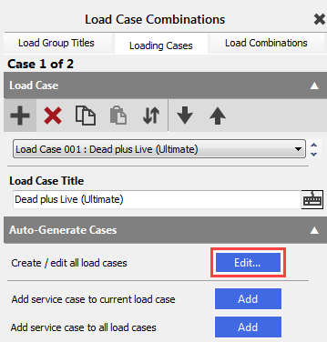
To open the Automatic Load Case Generator dialog, click on the Auto button of the Auto generate or update cases function in the Auto-Generate Cases field.
We can use the default Load Case Template to generate the load case
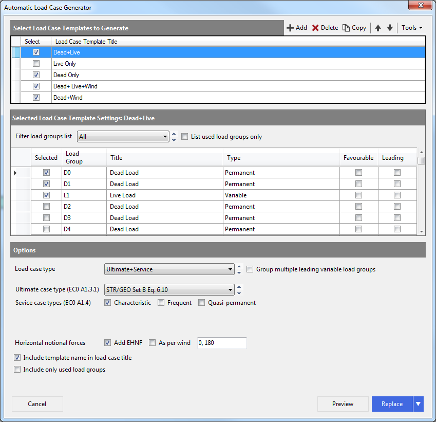
We will use the following templates and generation settings. To modify a template select it at first in the Select Load Case Templates to Generate table and update the settings below.
- Dead+Live
Selected Load Groups: D0, D1 and L1
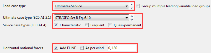
Load case type: Ultimate+Service
Ultimate case type: STR/GEO Set B eq. 6.10
Service case type: Characteristic
Horizontal notional forces: Add in 0 and 180 degrees
- Live Only
Selected Load Group: L1
Load case type: Service
Service case type: Characteristic
- Dead+Live+Wind
Selected Load Groups: D0, D1, L1 and W1
Load case type: Ultimate+Service
Ultimate case type: STR/GEO Set B eq. 6.10
Service case type: Characteristic
- Dead+Wind
Selected Load Groups: D0, D1 and W1
Load case type: Ultimate+Service
Ultimate case type: STR/GEO Set B eq. 6.10
Service case type: Characteristic
Horizontal notional forces: Add as per wind
To generate all load cases and replace the existing ones, click on the Replace button using drops down menu at Add
Now we have 9 loading cases.
Loading Combinations
Selecting the Load Combinations tab, we can check the generated loading cases and the used combination factors.
Using the dropdown menu or the arrow buttons you can move between the different loading cases.
Close the Load Case Combinations using the X button at the top right of the pane.
From the toolbar select Save to save our work so far.
Close Load Diagram dialogue by clicking on the X if it is still open.
Nodal Static Supports
From the Restraints file menu, select Nodal Static Supports.
Pick the bottom point of the columns and select the Pinned option.
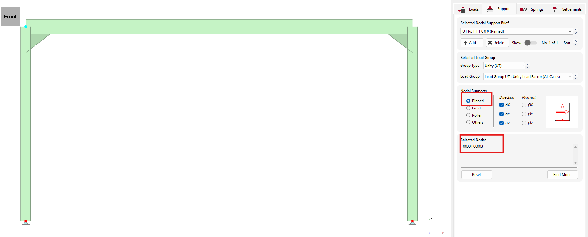
Close the Nodal
Static Supports dialogue with the Close ( ) button.
Analysing the frame
From the top menu select Analysis, then Static Analysis.
The file will be saved automatically, and the Analysis Type and License toolbar will now appear.
There are 5 possible types of analysis. Any analysis types that are not applicable to your frame will be deactivated. Any analysis types that do not match your licence will also be deactivated. Your licence limit for each analysis type is listed below each button.
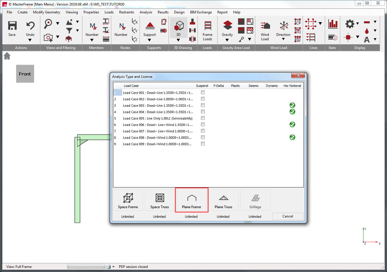
Select Plane
Frame ( ) and the frame will be analysed
Viewing and Printing the Graphical Results
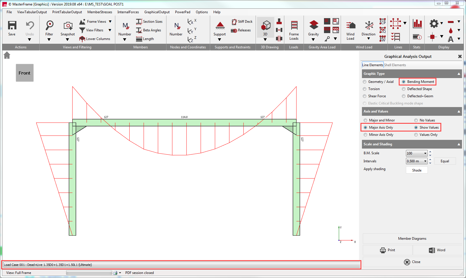
From the Results file menu select Graphical Analysis Results.
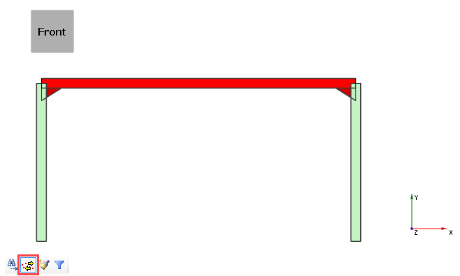
Place the frame in
front view by selecting the Front side of
the viewing cube  ).
).
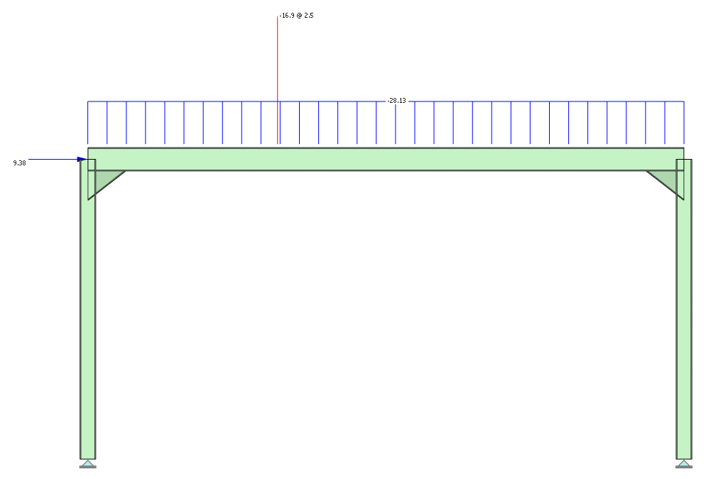
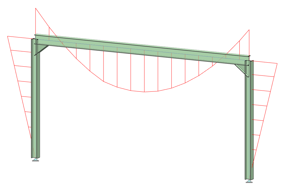
Select Bending Moment. We have no members bending about the Minor axis so select Major Axis Only on the right-hand panel and select Show Values.
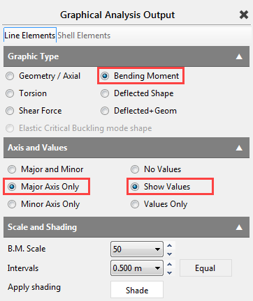
From the drop list, at the bottom of the screen, select and view each of the Load Cases including the envelopes.
Select Load Case 001: Dead plus Live (Ultimate)
Close Graphical Analysis Output dialogue by clicking on the X if it is still open.
Steel Design
Now we will design the members.
From the Design file menu, select the Steel Member Design option.
Checking the beam
Select Axially Loaded Members with Moments from the Integrated Design menu.
The Apply-to mode ( ) (bottom left of frame graphics
window) should be automatically selected. If not, select this mode.
) (bottom left of frame graphics
window) should be automatically selected. If not, select this mode.
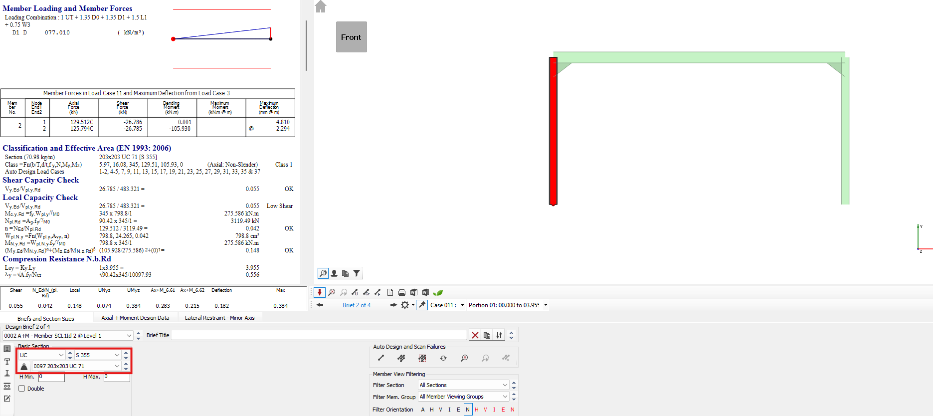
Apply the brief to the beam member by clicking on it.
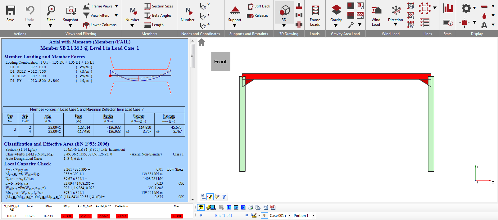
The window below the detailed results display us all the summaries of design checks expressed as a series of Utilisation values. Any values greater than 1.000 are failures and are highlighted in red. The detailed results are also on a blue background to indicate failure.
We have both buckling & deflection failures:
* Buckling Failure requires either a larger section or more restraint
* Deflection Failure requires either a stronger section or a change in the deflection limits
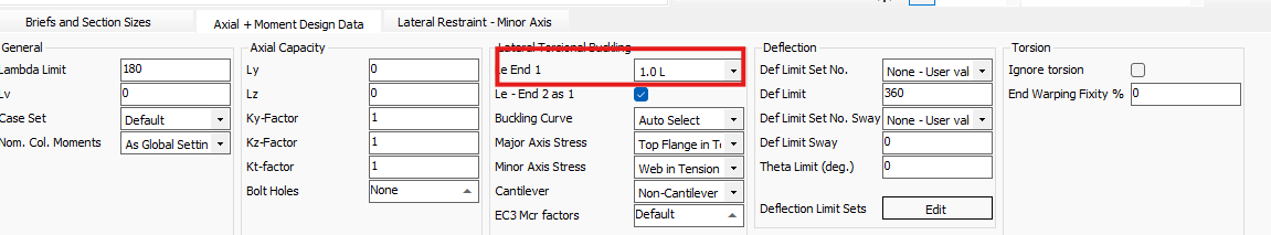
Move to the Axial + Moment Design Data tab below the results summary to check the used bending effective length, which is 1.0 L. That is fine.
Move forward to the Lateral Restraint - Minor Axis tab to set restraint conditions.
We will apply a lateral restraint at 2m. Change the value in the Variable Portion Lengths - End 1 to 2.0m.
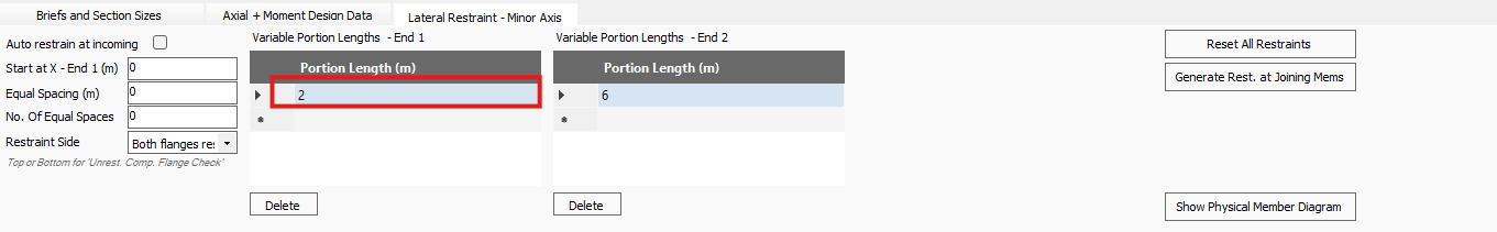
To restrain the beam only in 2m we must set the Variable Portion Lengths - End 2 to an equal or greater value than the remaining length of the beam.
Change the value in Variable Portion Lengths - End 2 to 6.0m which is past the end of the member.
The small graphic in the detailed result shows us that there
is only one restraint and two portions along the beam.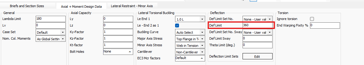
Clicking on the graphic or using the drop-down menu beside the brief selector we can switch between the portion and check the results of them.
Selecting the Variable Portion Lengths - End 2, we can see that the beam still fails the buckling and the deflection checks.
To set the deflection limits we must go back to the Axial + Moment Design Data tab.
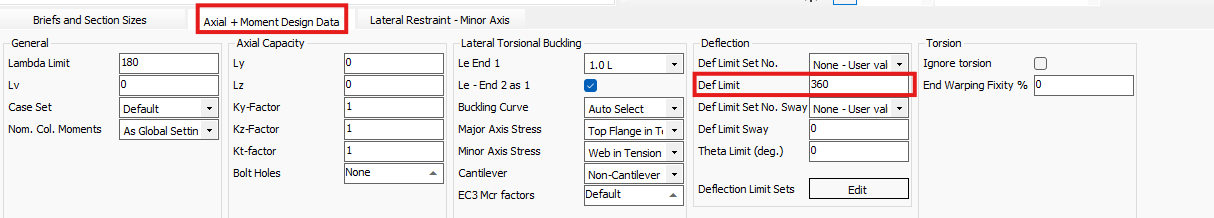
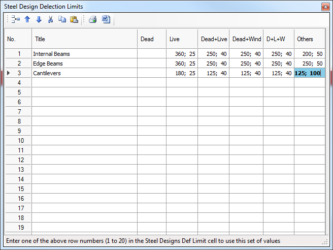
By changing the value in the Def Limit, we can set an overall L/X (for example L/360) limit which is used generally for every service case, or we can use a table number (1-19) which is referring to a row of the Steel Design Deflection Limits table. By clicking on the three dots button, we can edit the table and set different deflection limits for different type of members and loading cases.
Open the Deflection Limit Sets table and set the values as below.
In every cell, the first value is the L/X ration, the second is the exact deflection limit in mm.
Close the table with X button and change the value in Def Limit to 2 to use the 2nd row table limits.
Return to the Briefs and Section Sizes Tab.
Increase the section size using the drop-down list, or the spin buttons at the end of the drop list.
Turn on the Sort by weight ( ) option to order the section list by
weight.
) option to order the section list by
weight.
Now go up one at a time until you find a section that works. The 305x165 UB 46 is the lightest section which passes both ULS and SLS criteria.
Checking the columns
To check the column, we must take another design check.
Select Axially Loaded Members with Moments from the Integrated Design menu.
Apply the brief to the left column member by clicking on it.
Move to the Axial + Moment Design Data tab and set the buckling parameters and deflection limit.
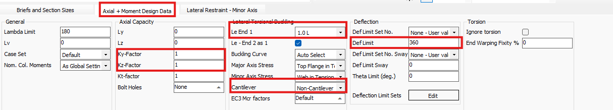
In our current example we leave the Flexural buckling (Kx and Ky) factors on default 1.0.
The bending effective length needs to be changed to 1.5 L and as it is a column, we have to change the critical moment calculation to Cantilever Warping Free mode by selecting from the drop-down table in the Cantilever tab.
Finally, we must set the Def Limit Set No. to 3 to use the previously set 3rd row table limits.
We can see that our column fails the buckling design checks.
Return to the Briefs and Section Sizes Tab.
In Sort by weight ( ) mode, increase the section size
until you find the first section that works. The 406x178 UB 60 is the
lightest section which passes both ULS and SLS critarias.
Change to copy mode and copy the design brief to the other column.
Change back to Search ( ) mode to avoid accidentally copy
briefs.
) mode to avoid accidentally copy
briefs.
The design settings and parameters are copied with the design brief, but the section size needs to be changed to 305x165 UB 54 to see it also works here. But it does not.
Increasing the section size, the first UB section which works is the 406x178 UB 67.
Go back to the left column by clicking on it as we are in Search (  ) mode.
We should consider using UC section instead of UB to find a lighter solution.
On the Briefs and Section Sizes tab,
change the section type to UC and while the Sort by weight ( ) mode is on, increase the section
size. The first UC section which works is the 203x203x UC 60
Go back to the right column and change section size to 203x203x UC 60.
It is still failing.
In Sort by weight
( ) mode, increase the section size.
The 203x203x UC 71 is fine.
) mode, increase the section size.
The 203x203x UC 71 is fine.
Go back again to the left column and change section size to 203x203x UC 71
. Now, all three members are passing the design checks.
But as a final step, we have to check that the design works for the revised analysis with the revised stiffness.
Select the Re-Analyse ( ) function on the Briefs and Section Sizes tab
to re-analyse the structure.
) function on the Briefs and Section Sizes tab
to re-analyse the structure.
Walk through the members by clicking on them and check the design. We can see that the two columns are fine but the beam in portion 2 is failed.
In Sort by weight ( ) mode, increase the section size.
The lightest section which works is the 305x165 UB 54.
Re-analyse and check again the design. Now all the members pass the design checks.
Second Order Analysis (Elastic Critical Load Factor αcr)
At this stage, with realistic section sizes, we can check the Elastic Critical Load Factor for the sway stability cases we created earlier.
From the Integrated Design menu select the Elastic Critical Load Factor design check.
An Elastic Critical Load Factor check is added to the design brief drop list.
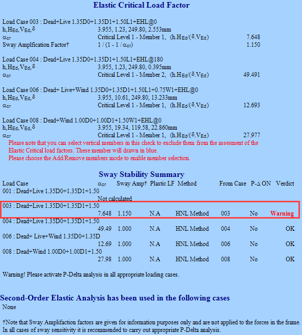
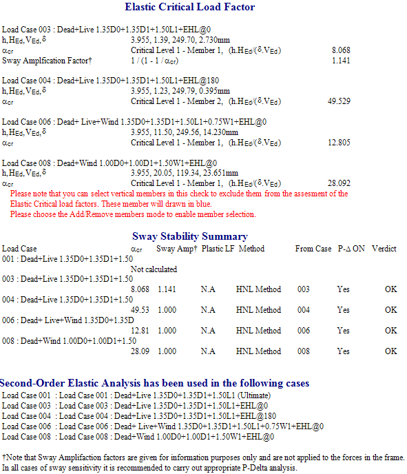
From the report, a warning is given against Load Cases 003
This load case has an αcr value of just less than 10, and hence it requires a Second-Order Elastic Analysis to be carried out on it.
Select Edit Frame from the Edit-View menu and save the file when requested.
From the Analysis
menu, select Second Order Analysis Options Per Load
Case. 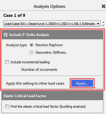
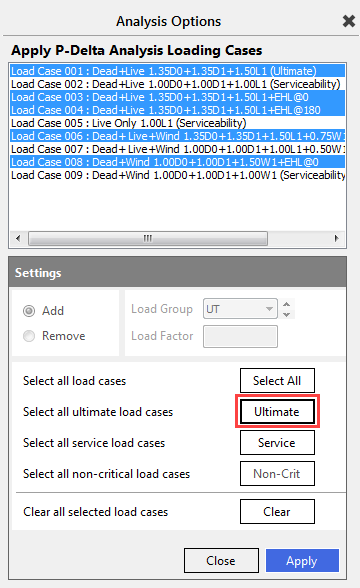
We can turn on the second order analysis case-by-case or clicking on the Apply button we can turn on for the selected once or we can use the group selection buttons to set the analysis for all the load cases.
Now we will use the Ultimate button, which will select all the ultimate load case. Clicking on the Apply button, the second-order analysis is turned on for all off the selected load cases.
Close the Analysis Options screen and re-analyse the frame.
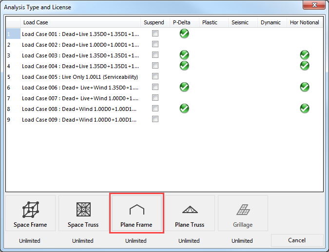
When the Analysis Type and License panel opens, green ticks indicate which analysis options are selected for which load case.
If during P-Delta Analysis the frame is unstable, a message will be displayed stating that the frame is too flexible. If the frame is stable, no message appears.
Select the Plane Frame analysis option from the menu. The frame will analyse without generating any warnings.
Select Steel Member Design from the Design menu.
Select the Elastic Critical Load Factor design brief from the design brief list.
This confirms that a Second Order Analysis has been carried out successfully in the load cases shown.
Select any member in the graphical
area to switch back to the member design view and click on the Scan for failures ( ) button.
The scan for failures will not reveal any failures, indicating that the members of the frame are passing all relevant design checks as set up in the design briefs. Thus, the design of the frame is complete.
End of Tutorial