
Wind Panels (Wall and Roof)
and Side Panel
The Wind Loading facilities enable the application of an area load in the direction normal to any planar surface. Similar to area loading, the wind loading is controlled by wind loading panel groups.
When we access the Wind Loading with a file where no previous wind loading has been applied, an empty wind load group is present. Each wind loading group applies to one planar surface. Each planar wind loaded surface of the building should have a separate group.
All the utilities required to set up wind panels are contained in the right hand panel.
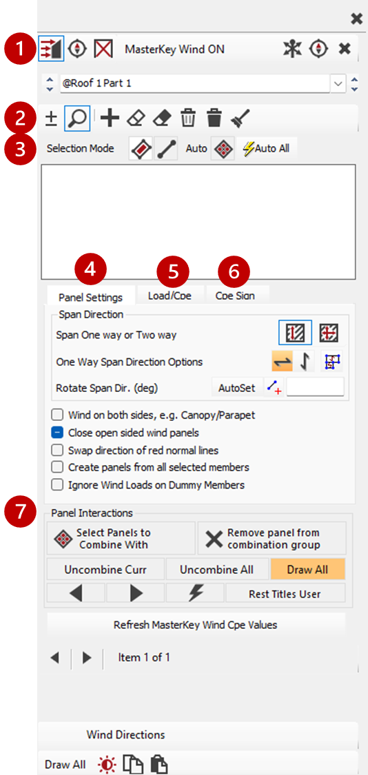
1. Top Row Toolbar
.png) Toggle On Wind Loading Options
Toggle On Wind Loading Options
.png) Wind Diagonals
Wind Diagonals
See 📄 Wind Load Reduction Members (Wind Diagonals)
.png) Bracing Members
Bracing Members
See 📄 Bracing Members (Members not in Panel)
.png) Wind Directions
Wind Directions
See 📄 Wind Directions Settings and Cpi Values
.png) Wind Site Data
Wind Site Data
See 📄 Site Data Wind Analysis (with SCIPHYR & Google Maps) Integration
2. Group Options Toolbar
.png) Add /Remove Wind Panels to a Wind Load Group
Add /Remove Wind Panels to a Wind Load Group
Add or remove individual panels within a group.
.png) Add a new Wind Load group
Add a new Wind Load group
Each Wind Load Group defines one planar surface of 1 or more panels contains the following information.
- All the wind panels in the planar surface
- Up to 8 different wind load intensities on the surface, using wind load groups W1 to W8, representing eight different wind directions. Each group applies a uniform load intensity to its surface.
- The side of the surface on which the wind loading is applied
- The load distribution characteristics on the surface, i.e. one way or two way spanning.
The wind zones and coefficients of external pressure are automatically calculated for each wind direction on each surface. The dynamic wind pressure is then calculated by the MasterKey Wind Analysis module to arrive at the wind loading on the surface.
- Each wind load group applies a uniform wind load intensity normal to a planar surface
- A wind load group can only apply to one planar surface
- All the members that define the panels in a planar surface should be added to the wind load member group. This is different from the gravity area loading application method where only the loaded members are added to the group. The wind loading calculations determine which members of the panels are loaded and which are not according to the direction of span.
- Unlike the gravity area loading method, bracing members do not need to be defined in a special bracing group, rather they are simply not added to the wind loading group and therefore do not affect the distribution of wind area loading.
- A member can belong to more than one wind load group.
- A panel must have three or four straight sides. A straight side of a panel can be made up of any number of individual elements.
.png) Clear current Wind Panel group / clear all groups
Clear current Wind Panel group / clear all groups
.png) Delete current Wind Panel group / delete all groups
Delete current Wind Panel group / delete all groups
3. Selection Mode Toolbar
 Pick panel or members to create wind surface
 Fast select panel / automatically create all panels
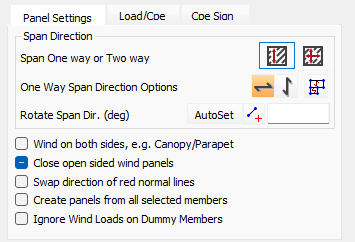
4. Panel Settings Tab
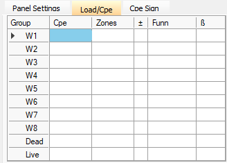
5. Load / Cpe Tab
See 📄 Load / Cpe Tab and Funnelling
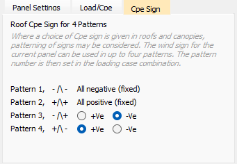
6. Cpe Sign Tab
See 📄 Cpe Sign Tab
7. Panel Interactions

Select Panels to Combine With / Remove Panels
You can combine panels so that 2 or 3 or more panels in an elevation or roof can act together. However, these panels must all be in the same planar surface.
For example, if a side elevation has a part of the elevation spanning vertically and part spanning horizontally, these would have to be defined as 2 separate panels. Since they are in the same elevation you want them to interact to give their true wind zones and relevant Cpes. Thus you would combine these 2 panels.
Whilst in one panel, click on the ‘Select Panels to Combine with’ button and then click on the second panel. Both panels should highlight in colour but only one panel will show the red perpendicular lines (indicating the outer surface). When the program examines the envelope of the building these 2 panels will be considered to act as one, even though their span directions are different
Update all panels for their interaction 
After adding new panels you can have the program update the interaction of all the panels. In doing this the program will reassess the interaction of the various panels around the building envelope and will update the zones and Cpe values.
Reset titles User / Auto
Each panel title can be entered by the user or alternatively you can let the program set its own titles.
- User: Can set the titles manually
- Auto: Allowing the program to set the titles automatically means that the panel interaction has been automatically assessed and a relevant title based on its orientation and position within the structure attributed to each panel. The title will have an ‘@’ symbol in front of it.
After alterations or additions to the panels, the panel titles can be updated by clicking on the ‘Reset Titles’ button.
.png) Update all panels for their interaction
Update all panels for their interaction
.png) Reset titles for each panel automatically
Reset titles for each panel automatically
.png) Draw all wind loading panels
Draw all wind loading panels
.png) Colour code wind loading per surface/intensity
Colour code wind loading per surface/intensity
.png) Copy brief to clipboard
Copy brief to clipboard
.png) Paste brief from clipboard
Paste brief from clipboard
Process of Adding Wind Panels
Switch to the Add/Remove button and then choose a selection mode. You can either;
- Pick individual panels
 As you move the cursor over the frame individual panels will be outlined in cyan. These can be added to the current group. Panels that have already been placed in a wind panel group will have a dark blue outline to distinguish them from unpicked panels. Add a new group for a new planar surface.
 - Pick individual members
 All the members around the perimeter of a panel should be selected. The outline members will show in red. Once the outline has been closed the panel should highlight in colour. The red lines perpendicular to the members of the surface indicate the side that the program sees as the outside face of the panel.
Note – in both the above options you can also window around panels/members to include them. - Auto Panel (Combined)

Fast selection of wind panels option not only allows you to pick a panel, but will automatically add a new group each time a panel is picked speeding up the process. - Auto All

Allows the program to attempt to automatically apply wind panels to the envelope of the whole frame. You must ensure the perimeter of the frame has been split into rectangular and triangular panels for this function to work well. Dummy members may need to be added in locations to facilitate this.
Ideally you want the complete external envelope of the building to be closed in by wind panels. Hence the program, when assessing the wind zones, can distinguish between the interaction of adjacent panels and so produce the most accurate wind loading around the building for each wind direction being considered.
Check the application of the wind loading around the building using the Wind load display (📄 The Wind Loading toolbar) buttons in the top toolbar – see chapter on Getting Started. Show the panels and their pressure values for each wind direction. Positive values will be external pressures (usually coloured yellow) and negative values will be external suctions (usually coloured green).