Designing Goal Post and Box Frames in MasterSeries for Domestic Openings
In MasterSeries, steel goal post or box frames often used over rear extension knock-throughs or bi-fold doors are a very common design scenario. Where retaining masonry buttressing piers is unviable or unwanted architecturally, structural engineers must introduce steel moment frames, specifically goalpost frame (2 moment connections) or a box frame (4 moment connections) to restore required lateral sway stiffness and safely re-route vertical and horizontal load paths down to the foundations
In these frames, lateral sway stiffness and serviceability deflection limits (SLS) almost always govern member section selection over ultimate limit state (ULS) bending strength. Supporting delicate architectural elements, such as full-height bi-fold glazing, often requires restricting live-load vertical deflections to tight absolute limits.
Below is a technical guide to setting up, loading, and verifying domestic steel frames in MasterSeries.
Structural Stability, Base Fixity & Lateral Sway Checks
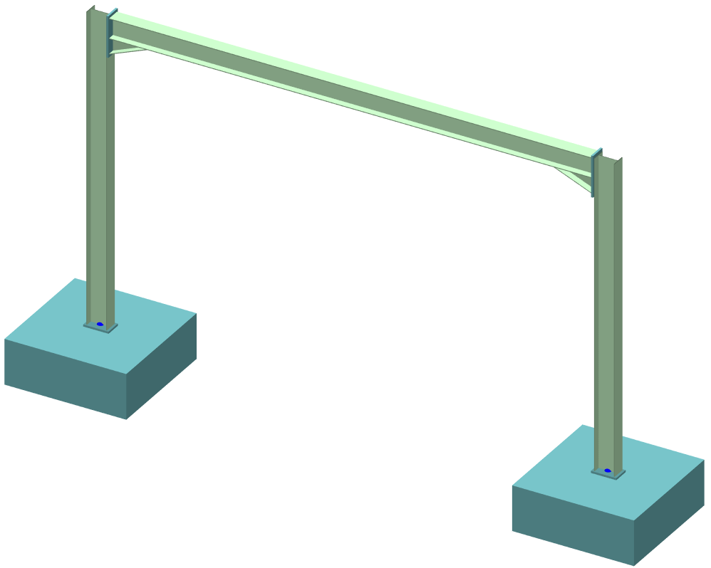
Because goal post frames lack diagonal bracing across the opening, lateral stability depends entirely on the frame’s bending stiffness, moment-resisting eaves joints, and column base restraints.
In domestic structural design, a typical steel goalpost frame (a 3-sided moment frame) relies on two rigid moment connections at the top beam-to-column joints to provide lateral sway stability, while the column bases resting on foundation pads are treated as pinned joints
- Unbalanced Horizontal Base Thrust: Because the base lacks a rigid moment connection to the ground, horizontal shear forces (generated by vertical loads and lateral wind sway) create equal and opposite horizontal thrusts at the bottom of each column.
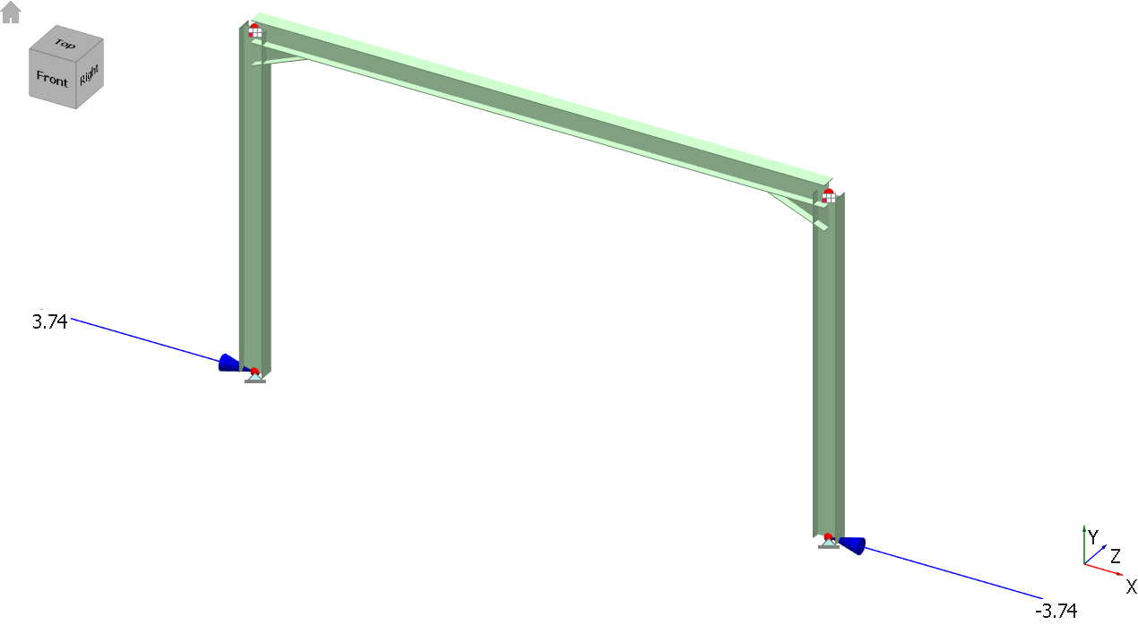
- Foundation Sizing: Column base shear and overturning moments must be resisted entirely by a combination of friction beneath the concrete footing and passive soil resistance. This is why goalpost frames generally require large, discrete mass-concrete pad footings beneath each column.
- Comparison with Box Frames: If a project cannot accommodate large pad footings (for example, directly adjacent to a party wall boundary), engineers frequently switch to a 4-sided box frame. A box frame introduces a bottom steel ground beam with 4 moment connections, which internally equilibrates the horizontal base thrust and distributes point loads uniformly across existing or new strip footings.
Eccentric Masonry Loads & Torsion on Top Beams
In domestic extensions, goal post top beams routinely carry eccentric masonry walls (e.g., outer leaf brickwork resting on a welded bottom plate or flange nib).
When designing top beams for domestic goalpost or box frames (or standard steel lintels), eccentric loading on the top beam is a critical design issue that directly impacts member stability, stress levels, and deflection. A common example would be supporting a 100mm brick outer leaf and 100mm block inner leaf on parallel beams or a single wide-flanged section, where the load centroid of one leaf does not align with the beam’s shear center.
Load Path & Overturning Effect
Out-of-plane or eccentric loading on the horizontal beam induces a twisting moment (torsion) along the beam. This torsion transfers into the beam-column joints as an out-of-plane bending moment, causing minor-axis bending, twisting, or lateral sway in the supporting columns.
- Open Sections vs. Closed Sections: Universal Beams (UB) or Parallel Flange Channels (PFC) are open sections with low torsional stiffness. Small load eccentricities can induce severe twisting, causing the beam to fail in torsion or exceed the rotational deflection limit. Where torsional demands are significant, closed hollow sections (RHS/SHS) are often recommended.
Applying Torque Eccentricity (Torq ecc):
- Go to Loads > Member Loading in MasterFrame.
Select the top beam and insert a Torq ecc command above the applied vertical UDLs/point loads in the load list.
- Sequential Load Rule: Torq ecc. is an offset property that applies strictly to subsequent member loads listed below it in the loading sequence.

- Sequential Load Rule: Torq ecc. is an offset property that applies strictly to subsequent member loads listed below it in the loading sequence.
Enter the eccentricity offset (ex, ey) in metres) measured from the section's shear centre to the line of action of the load (not the geometric centroid).
- For doubly symmetric sections (UB/UC/RHS), the shear centre coincides with the centroid.
- For asymmetrical sections (PFC channels, angles), the shear centre lies outside the web/flange profile, and eccentricity inputs must account for this offset.
- Enabling Torsion Checks: In MasterKey Steel Design, ensure the torsion check toggle (typically Torsion with Ends Free to Warp) is activated under the Axial with Moment design brief. Support nodes must be provided with rotational torsional restraint (thetax) / (theta_z) to resolve induced twisting moments.
Column Rotational Instability
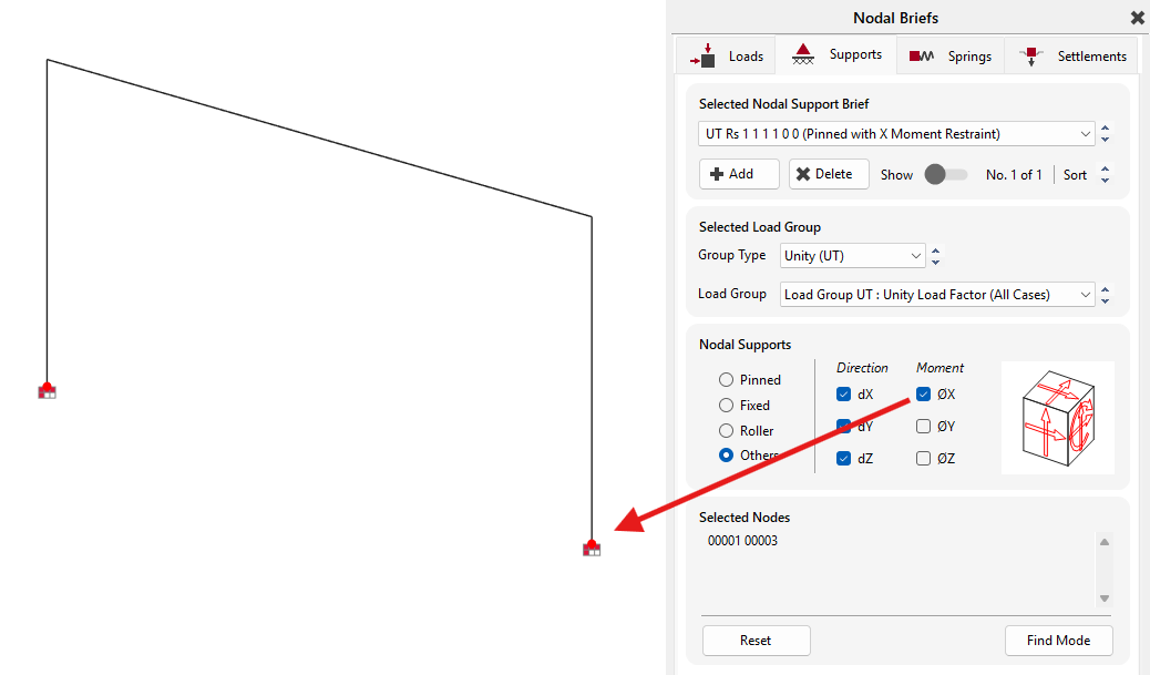
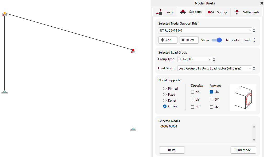
A common issue in goal post models occurs when column bases are modeled as pinned.
In the Nodal Static Supports menu, to prevent the frame from globally rotating you can apply a rotational restraint θx at
- the column bases
- or the column heads
- the column bases
Steel Design Considerations
Once frame analysis is complete, member checks are carried out in MasterKey Steel Design.
Considering Torsion within the Design Brief Selection
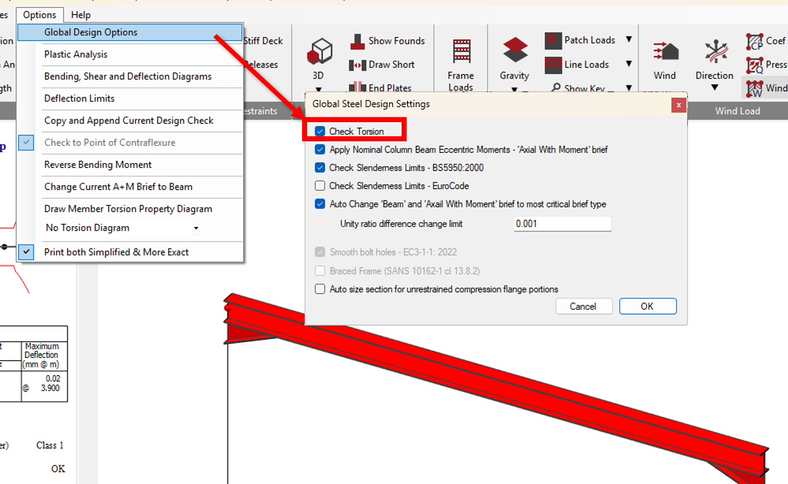
Select an Axial with Moments design brief and enable the Check Torsion option is enabled within the Global Steel Design Settings options.
End Warping Fixity
Keep 'Ignore Torsion' turned off with 'End Warping Fixity' set to 0%. Selecting "100%" is generally unrealistic for standard bolted end-plate connections unless the beam is encased in mass concrete.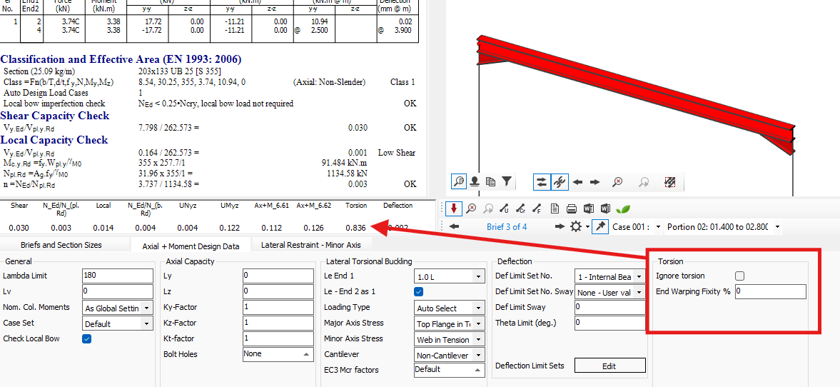
SCI P385 / Eurocode Scope Limitations
Dedicated steel design checks per SCI P385 / BS EN 1993-1-1 incorporate warping stiffness (Iw) and combined warping-bending cross-section checks to ensure full structural compliance
MasterSeries checks steel torsion in accordance with SCI P385 / BS EN 1993-1-1. Under SCI guidance, design checks are strictly valid only when:
- The torsion diagram is uniform (constant torque) across the member length, OR
- The net area under the torsion diagram sums to zero.
Rotational Deflection Limit (θ Limit)
The software checks the cross-sectional rotation against a default limit of 2.0 degrees. This is the recognized SCI threshold to prevent damage or out-of-plane cracking in supported masonry.
Limitation: If the torsion diagram shape does not meet these criteria, MasterSeries will report that the torsion arrangement falls outside the scope of published SCI design guidance.
Practical Cautions & Design Recommendations
Open Sections vs. Closed Sections
Open I-sections (UB/UC) and channels (PFC) have very low torsional stiffness (J) and fail rapidly under small eccentricities due to warping stresses and excessive rotation. If an open section fails the 2.0-degree limit or combined stress checks, consider switching to a closed section (RHS/SHS) or providing intermediate lateral/torsional restraints.
Ignoring Torsion Check for Floor Diaphragm Tie-Backs
Connecting the top compression flange directly to timber floor joists or timber deck diaphragms using proprietary restraint straps may be considered to provide lateral and rotational restraint, preventing unrestrained LTB and excessive rotation.
Technical Summary
Parameter / Setting | MasterSeries Setting / Behavior |
|---|---|
Load Input | Torq ecc. in Member Loading (measured from Shear Centre) |
Column Base Stability | Restrain θx at pinned supports / column head to prevent global rotation |
Design Brief | Axial with Moments brief $\rightarrow$ Enable Check Torsion |
Warping Boundary | Set to Ends Free to Warp |
Rotation Threshold | Checked against 2.0deg limit |
Code Scope | SCI P385 / EC3 (requires constant torque or zero-sum diagram) |
Steel Connection Design & SCI Green Book Limits
Corner joints connecting the steel beams to the columns, and baseplates are designed using the integrated MasterKey Steel Connection Design module.
Beam to Column Moment Connection
MasterFrame analyses members along their centerlines, but when linked to the Steel Connections module, internal moments and shear forces are automatically evaluated at the face of the column rather than the centerline node, reducing the design moment slightly.

Baseplate Connection Design Check

Foundation Designs and Checks
Concrete Pad Foundation Checks
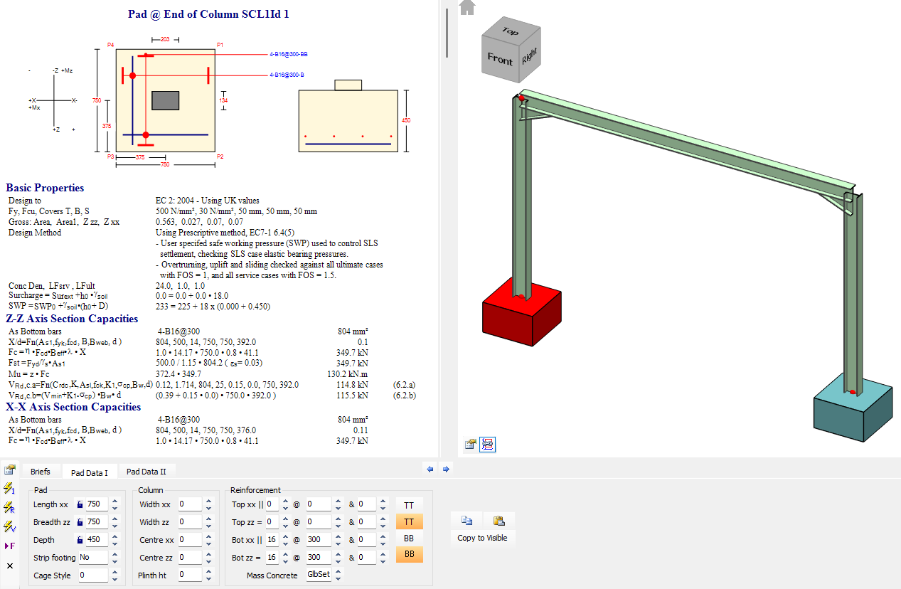
Base reactions populate MasterKey Concrete Pad Foundations, which verifies soil bearing pressures under combined axial load, shear, and bi-axial overturning moments. The module also carries out base uplift checks and stability factors against overturning and sliding.
4-Sided Picture Frames (Ground Beams on Soil Springs)
Where low bearing capacity soils, high concentrated loads, or boundary constraints prevent the use of traditional pad footings, engineers frequently incorporate concrete encased steel beams to bear onto the existing ground / foundations.
A box frame comprises four steel members - a top beam, two vertical columns, and a bottom steel ground beam, joined by four moment-resisting corner connections
With four rigid joints, box frames exhibit significantly higher global sway stiffness. This increased rigidity allows for shallower, lighter steel members, which helps maximise room head-height.
Modeling a ground beam on continuous soil requires accounting for soil-structure interaction, as stiffer soils attract higher localized bearing pressures near columns while stiffer beams distribute loads more evenly.
If the goal post includes a bottom ground beam (forming a full 4-sided 'picture frame' or box frame):
Analytically Segmenting the Ground Beam
Split the bottom member into short 1D segments (0.5m - 1.0m) and apply discrete vertical nodal springs.
Nodal Vertical Spring Supports
Apply vertical spring supports to each intermediate node.

Calculate vertical spring stiffness (k) based on soil subgrade modulus (Ks) and spring tributary area
- K(kN/m) = ks (kN/m3) × b (m) × Ltrib (m)
MasterFrame performs a non-linear iterative analysis to distribute beam loads into the soil springs based on relative beam and soil stiffness.
Plan Restraints (dX, dZ)
Because soil springs provide zero horizontal friction, static horizontal restraints (dX, dZ) must be applied at a minimum of two base nodes to prevent rigid-body sliding and zero-pivot solver errors.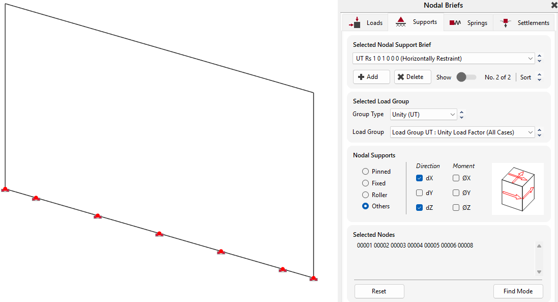
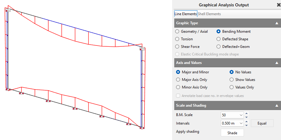
Bending Moment Diagram of a Box Frame
Justifying Masonry Walls with In-Plane Racking Loads
Retaining partial masonry return walls or buttressing piers can avoid the need for full steel moment frames. However, traditional linear elastic code checks for laterally loaded masonry with multiple door and window openings are often overly conservative.
Using MasterSeries Advanced Yield Line Analysis (AYLA) Checks
MasterKey Masonry Design uses an iterative yield-line virtual work algorithm to evaluate out-of-plane lateral panel capacities. Model masonry panels containing up to 10 openings (windows, doors) alongside vertical wind posts. AYLA evaluates the true yield-line failure mechanism, helping engineers justify existing host walls.
In-Plane Wind & Racking Loads Transferred into a Buttress Wall
MasterSeries Masonry design is a separate module which carried out a single 2d wall panel analysis. If a wall panel receives wind loading from a perpendicular buttress/return wall, MasterKey Masonry does not automatically transfer 3D wind reactions from one panel brief to another. You will need to manually transfer the reaction as an in-plane shear force and overturning moment.
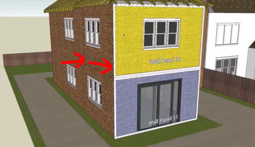
To perform a design check for a rear wall panel with openings, you should follow these key steps as demonstrated in the video (jump to 19:06 Rear Wall Panels 10 & 11 Including Resisting In-Plane Shear Forces and Moments from Adjacent Walls)
- Calculate Global Reactions: Determine the in-plane shear force (Qz) and in-plane overturning moment (Mz) acting at the head/base of the buttress wall from your global structural load takedown.
Apply In-Plane Loads: Open the design brief for the buttress wall. Under the Lateral Loads input tab, enter and .
- Apply racking shear forces Qz (design in-plane shear) as a total load in kN (rather than kN/m run) on the side of the wall
- Include the Mz (design in-plane overturning moment) derived from these shear forces, using a lever arm taken at the mid-height of the wall.
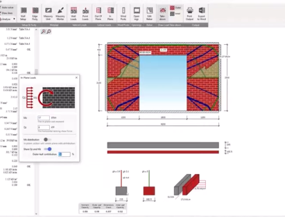
Design Verification: The software checks the in-plane bed-joint shear stress and evaluates combined vertical compression and flexural tension across the length of the buttress leaf.
- The software allows you to distribute loads between the inner and outer leaves (e.g., 50/50 distribution) to check the structural integrity.
Engineering Responsibility & Recommended Escalation
Engineering Responsibility Reminder
Please note: MasterSeries software outputs provide structural analysis calculations and code verification checks based on user input. Overall engineering assumptions, site survey accuracy, condition assessment of existing host masonry, temporary works sequencing (propping/needling), and Party Wall Act compliance remain the sole responsibility of the competent structural engineer.
Recommended Escalation Message
Please contact sales@masterseries.com with your licence details and a short description of what you are trying to model or design. The team can confirm whether this is possible within your current licence, or whether a trial, rental or upgrade would be more suitable.
Recommended Software Environment & Module Selection
MasterSeries 'Lite' aka PowerPad Suite
For small consultancies and sole traders carrying out domestic alterations, we recommend the MasterSeries Lite aka PowerPad suite, which includes
- Space Frame Analysis Software | MasterFrame | MasterSeries: Goal post / box frames are modelled as 1D wireframe elements
- Steel Design Software | Structural Engineering Software | MasterSeries:
- Steel Connection Design Software | Moment Connections | MasterSeries:
- MasterKey Masonry Design: MasterSeries Lite aka PowerPad includes a 'Lite' Version of the Masonry Design Module. The full version with the AYLA, can be obtained via an optional upgrade.