Understanding Toe Plate Connection Designs in MasterSeries
Beam-to-beam flexible end plate simple connections with flange toe plates
From 📄 Beam-to-beam End Plate Simple Connection with Flange Toe Plate
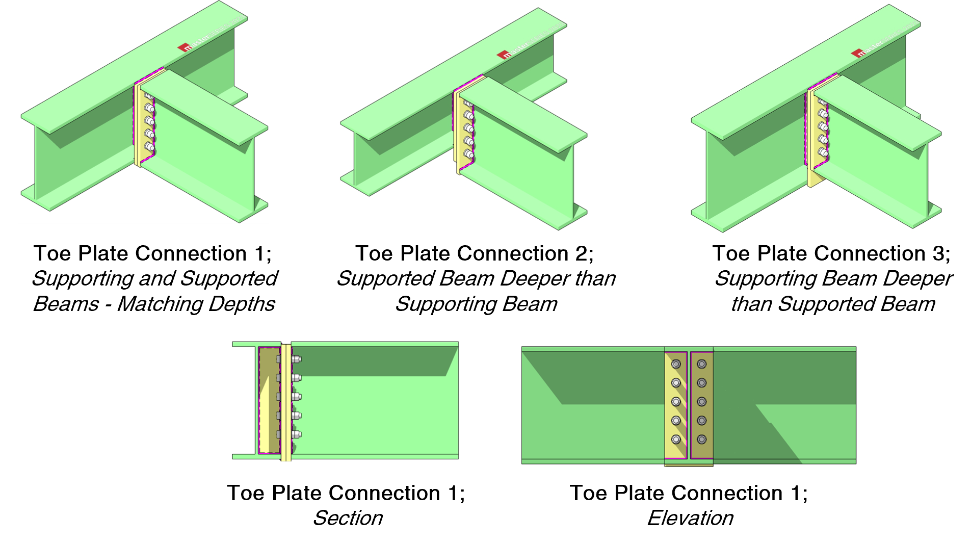
What’s a Toe Plate Connection?
Normally, when two steel beams meet, the smaller “supported beam” connects to the web (the flat middle part) of the bigger “supporting beam.”
A toe plate connection instead attaches the smaller beam to the outside of the flanges (the top and bottom edges) of the bigger beam.
This helps:
Avoid notching or cutting beams.
Makes installation easier (no “swinging in” between flanges).
Provides a neat simple end-plate connection option.
Why It’s More Complicated
Moving the connection from the web to the flange changes how the forces flow through the supporting beam.
That small sideways offset (from the beam web to the flange tip) introduces a torsional moment - a twisting effect on the supporting beam.
If we call that offset ecc and the end shear VEd, then the twisting torque is:
Mtoe,Ed=ecc×VEd
“I” beams aren’t great at resisting torsion, so even a small torque can make the supporting beam twist a lot.
The Engineering Trick
To stop the supporting beam from twisting too much, the toe plate and supported beam are treated like a moment connection, not just a pinned joint.
That might sound odd (since simple beams are supposed to be pinned), but it works because:
The supported beam actually helps brace the supporting beam against twisting.
The torsion reduces drastically - finite element tests showed twisting going from 10° down to about 1° just by making the connection moment-resisting.
So, the supported beam acts like a stabilising arm.

(a) (b)
Figure 1. Deflected shape at 10x magnification.
- (a) Toe plate with pure pin at supported beam end. Supported exhibits 10.27 degree torsion rotation.
- (b) Toe plate with 10mm supported beam full depth end plate. Supporting beam is effectively torsionally restrained by the supported beam and exhibits 1.16 degree torsion rotation.
Key Point: It Depends on Stiffness
Whether this behaves as a “moment” or “simple” connection depends on how stiff the supporting beam system is.
If the supporting beam system is flexible in torsion, the supported beam still behaves like a simply supported beam (no hogging moment develops).
If the supporting beam is very stiff in torsion, the supported beam might develop some hogging (negative) moment at its end.
That’s not ideal because it puts compression in the bottom flange and can require extra stiffeners.
Supporting beam open sections like I sections and channel sections are flexible in torsion, however as the supported beam moves closer to the supporting beam end, this torsional stiffness will likely increase. Furthermore if you have supported beams on both sides of the supporting beam, then this torsional flexibility will be significantly affected. In both these cases with the toe plate connection, the simple support assumption should be challenged.
Finite element examples showed that:
A 10 mm end plate made the connection stiff enough to stop torsion but didn’t make the supported beam fixed.
If you have beams on both sides of the supporting beam (a “through beam”), significant hogging moment (up to 40% of the sagging moment) can develop - so it should be treated carefully or modelled as a simple connection instead.
How to activate the Toe-Plate connection configuration
The toe plate option is part of the Beam-to-Beam Flexible End Plate Simple connection type. It is only available for Eurocode design and will not appear for British Standard design. It can be chosen for each supported beam independently from the 'End Plate> Flange Toe Plate' option shown below.

Two Design Options in MasterSeries
You can choose either design approach per connection:
Moment Connection
Used when you want the supported beam to restrain torsion in the supporting beam.
Both plates must be full depth, welded on both flanges.
MasterSeries checks both the supported and toe plates separately for moment + shear.
Simple (Shear-Only) Connection
Used when you just want a pin-type connection.
The supported beam end plate can be partial depth.
The torsional moment Mtoe,Ed=ecc×VEd is assumed to act on the toe plate and its welds.
The software reminds you to check torsion in the supporting beam yourself.

Summary
Moving the connection to the flange makes erection easier, but introduces torsion.
If you make the connection moment-resisting, that torsion almost disappears.
If you make it simple, the supporting beam needs to handle the torsion on its own.
MasterSeries lets you choose which behaviour to design for - but you, as the engineer, must understand which case fits your structure.