Pad Foundation Design Group Management
The design of multiple pad foundations in MasterSeries is executed within the MasterKey Concrete Beam, Column and Pad Design module, which integrates with MasterFrame. This process involves generating the necessary load combinations in the analysis phase and then utilising concrete design groups to rationalise the final size and reinforcement across multiple pads.
1. Generating Load Combinations for Pad Foundation Design
To carry out the pad foundation design, the system relies on the analysis results (reactions) obtained from the MasterFrame model. This requires defining appropriate load cases and combinations:
- Load Case Combinations: In MasterFrame, you create and analyze Combinations of Actions directly, rather than generating basic cases and combining results afterward.
- Foundation Specific Requirements: Load combinations must include both Ultimate Limit State (ULS) cases (for strength checks) and Serviceability Limit State (SLS) cases (for checking bearing stresses against the safe working pressure, SWP).
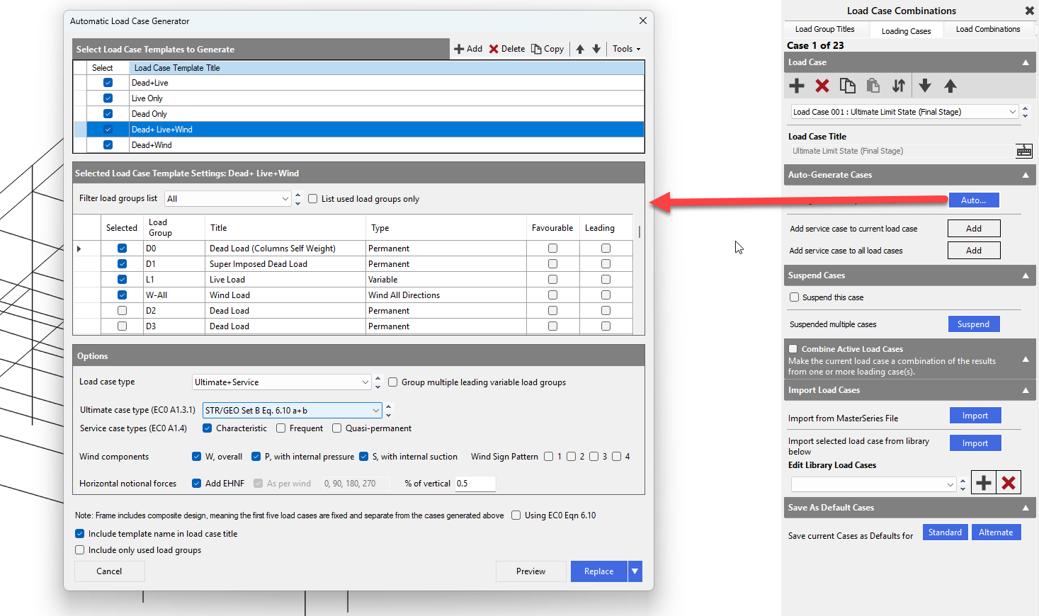
- Automatic Generation: You can use the Automatic Load Case Generator function to quickly create the required combinations based on the chosen design code (e.g., Eurocode).
2. Designing Pad Foundations
Once the frame analysis is complete with the necessary load combinations, you can enter the concrete design module:
- Access the Module: Navigate to the Design menu and select the Concrete Beam, Column and Pad Design option. The program automatically associates a pad foundation with every column base that has a support.
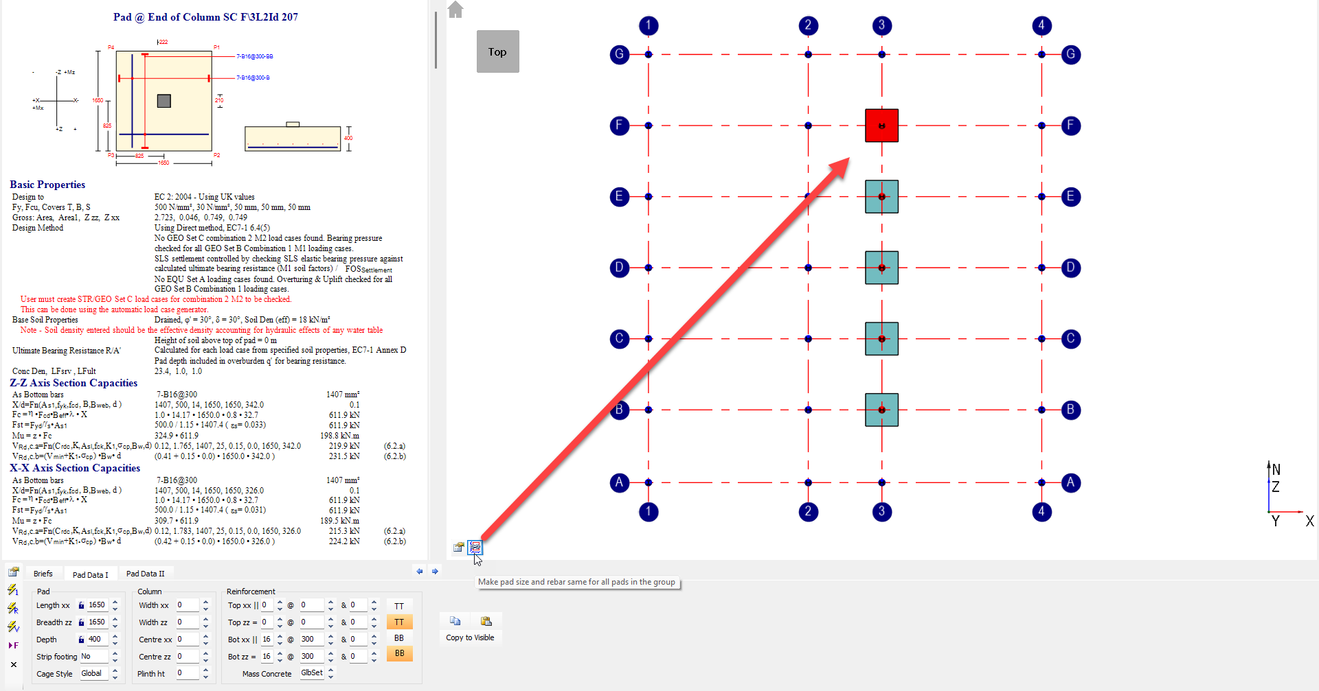
- Selecting a Pad: You can select a pad for review or design by clicking on the bottom of the corresponding column in the graphic area.
- Geotechnical Input: In the default settings or the pad-specific data, you must define the soil data. This typically includes the Safe Working Pressure (SWP) in kN/m^2 (the unfactored service bearing pressure). Other geotechnical inputs include soil density and coefficient of friction.
- Eurocode 7 Methods (MasterSeries 2023+): If using the Eurocode 7 Direct Method, MasterFrame incorporates additional load combinations relevant for calculating the ultimate and serviceability bearing capacities based on input soil properties. If no matching service case (load factors ≤ 1.0) is found, the program can estimate the service forces from ultimate forces by reducing them using an appropriate factor.
- Design Parameters: Key design parameters can be adjusted in the Pad Data I tab, including pad dimensions (Length XX, Breadth ZZ, Depth) and reinforcement (Top/Bottom bars, diameter, and pitch).
- Design Methods: You can choose to design the pad as mass concrete (no rebar) or reinforced concrete. The program performs checks for bearing, overturning, and sliding failures, alongside structural checks for shear and bending.
- AutoDesign: The module features AutoDesign tools that allow you to specify minimum and maximum bar diameters and pitches for the reinforcement.
Initial Rationalisation of your Design Groups
Option 1 (recommended) - Use the Auto-Design Feature and Group based on Pad Sizes
Before setting up any Design Groups, you can enter the Concrete Pad Design module. Before you enter the Pad Design module, you will be able to set some Global Parameters for the Pad Design.
Within the Concrete Pad Design module, select Auto Design All Visible members in the Current Frame.

This will run through all Pad Designs to allow for the sizing of each individual elements. You may wish to define a global depth, then 'Lock the Depth of Pad' under Pad Data 1 Tab.


The software will auto-design each pad individually. 
You can then review the Automatically sized foundations, then rationalise your design groups from here based on their sizes.
Option 2 - Manually Review the Support Reactions
then Create Design Groups based on similar support reactions
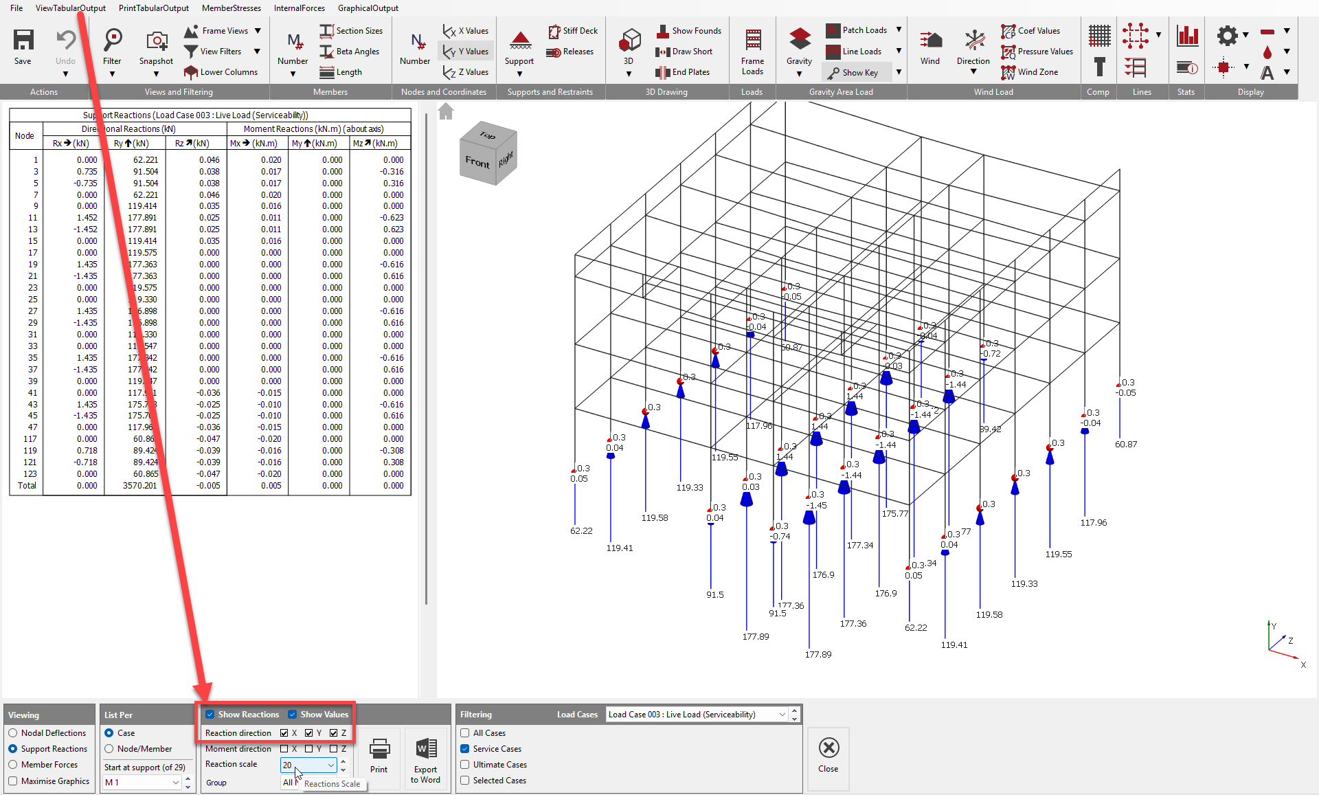
You have the ability to review your Support Reactions from within the View Tabular Output to set up your initial Pad Foundation Design Groups. Within here you can highlight the Maximum (shown below) and Minimum Loads from the various Load Cases.
You can also review Horizontal Reactions, and Minimum (i.e. uplift) reactions for example at braced bays, creating additional Pad Design groups if required.
3. Rationalising Design using Concrete Design Groups
To simplify detailing and construction by making multiple pad foundations the same size and reinforcement layout, you should use Concrete Member Design Groups.
Concrete design groups allow you to define a common set of design parameters for a subset of members, or, critically, specify that a group of members is to be designed for the same reinforcement, concrete grade, cover, and size.
- Accessing Concrete Pad Design Groups: You can access the groups within:
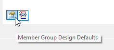
- Concrete Design module: via the Member Group Design Defaults icon.
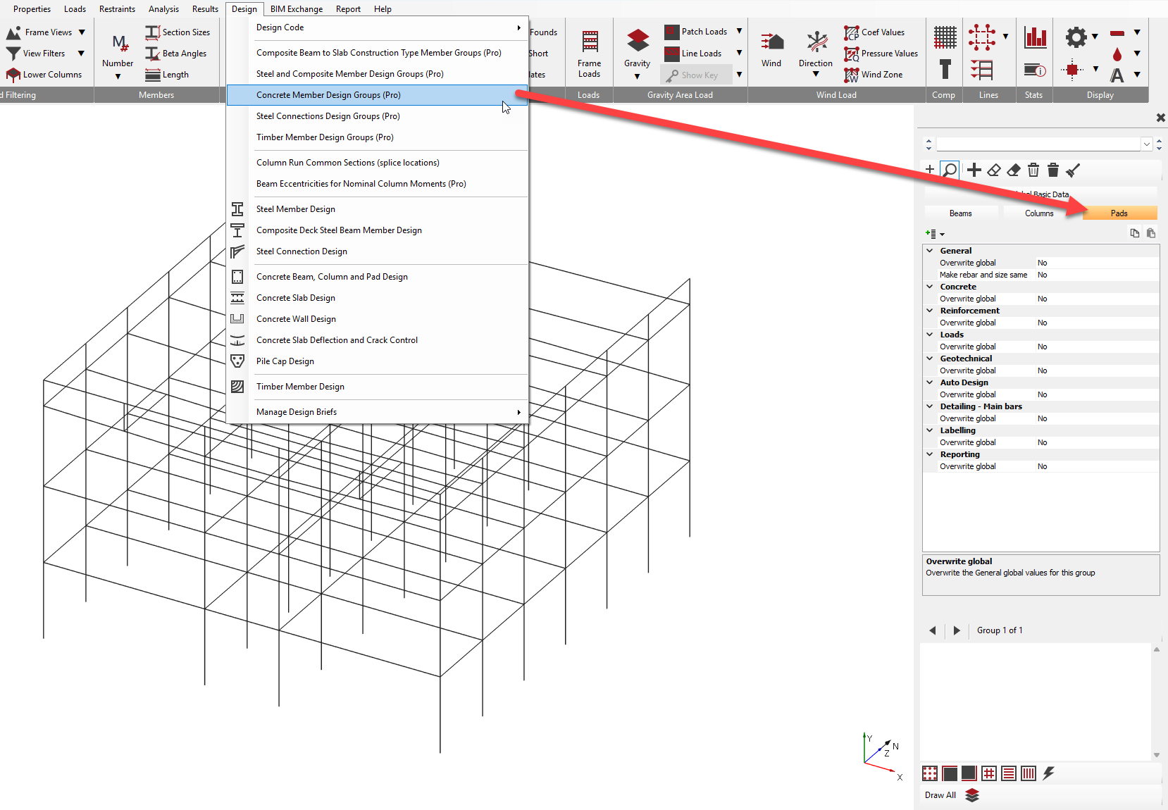
- MasterFrame: you can access via Design > Concrete Member Design Groups (Pro).
- Concrete Design module: via the Member Group Design Defaults icon.
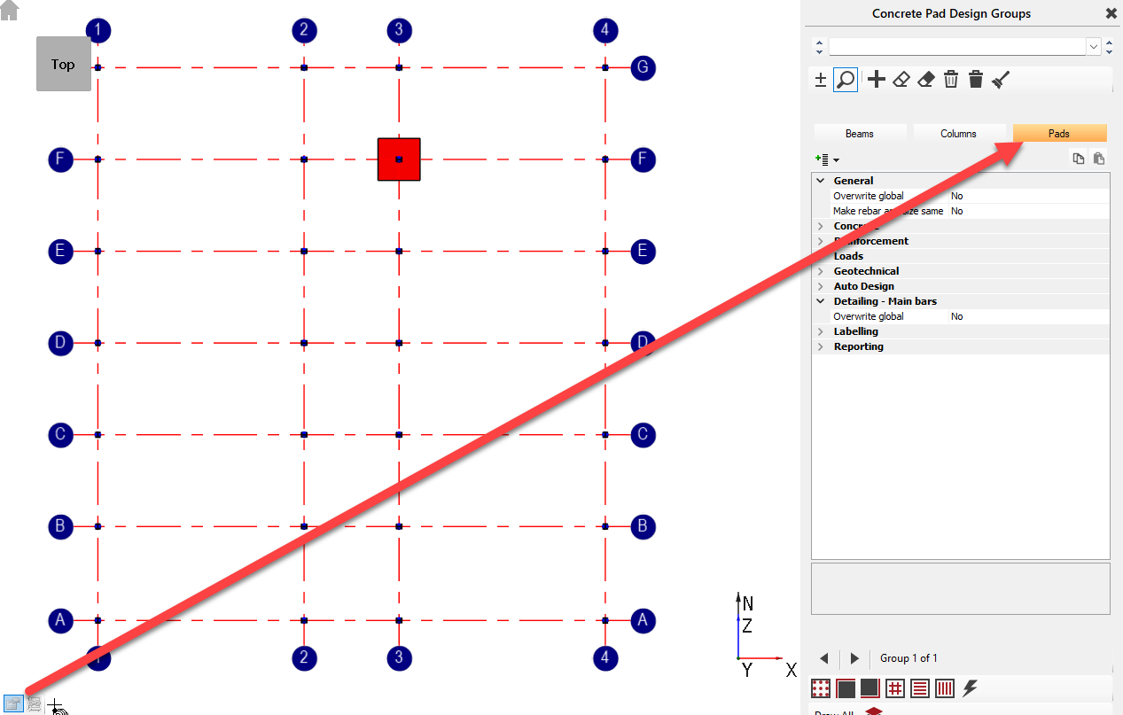
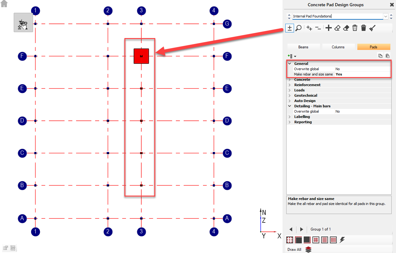
- Defining a Pad Group: Within the design group interface, select the Pads tab. To define a group, you must select the columns/pads to be included.
- It is recommended to Auto Design all your Pads initially, then group similar sized pads together. Use the guidance outlined within the previous step, titled Initial Rationalisation of your Design Groups.
- It is recommended to Auto Design all your Pads initially, then group similar sized pads together. Use the guidance outlined within the previous step, titled Initial Rationalisation of your Design Groups.
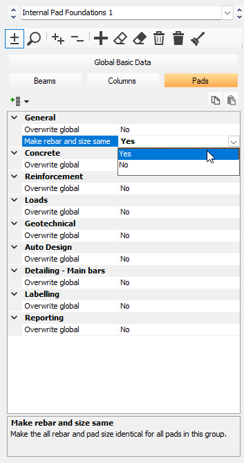
- Setting Group Parameters: For the defined group, you can choose to override global parameters (such as the Safe Working Pressure). Most importantly, you can set the group to "make rebar and size the same for all the pads".
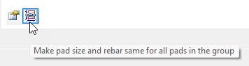
- Auto Design of the Group: Ensure the 'Make Pad Size' icon is turned on, then select the relevant Pad Design Group.
When the Auto Design function is executed, all pads within that specific group will be designed to the same final dimensions and reinforcement specifications, based on the dominant forces experienced by the most critical pad in that group. This achieves the necessary rationalisation. - Output: After the design is complete, you can export the pad design outlines along with the reinforcement details to a DXF or DWG file, or generate a full bar schedule.