Mastering Pile Cap Design Methodologies: Optimising Capacity and Depth
The MasterRC Pile Cap Design module is designed for the analysis, design, detailing, scheduling, and drafting of standard pile caps supporting 2 to 9 pile groups. It is designed interactively, meaning that as input data is altered, the calculations and graphics update immediately.
A. Core Design Code Selection
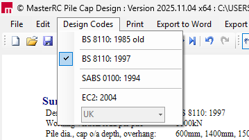
The software allows users to design pile caps according to multiple internationally recognized standards. The selected code is applied globally to all pile cap design briefs within a single file.
- Supported Design Codes: Pile caps can be designed to BS 8110 (1985 or 1997 versions), the South African Code SABS 0100 (1984 or 1994 versions), or Eurocode 2 (EC2) (2004 version).
B. Choosing the Optimal Design Methodology
The module provides two fundamental design methodologies, allowing the user to select the appropriate method based on the pile cap geometry (specifically, the span-to-depth ratio).
| Methodology | Description and Applicability |
| Beam Theory (Beam Analogy) | Treats the pile cap as a standard concrete beam for bending and shear design, based on the assumptions of Euler-Bernoulli beam theory. This method is typically valid when the depth is small compared to the span. |
| Strut & Tie Method (Truss Analogy) | Models the complex stress patterns within the reinforced concrete element as a truss form, idealising compressive zones as struts (concrete) and tensile zones as ties (reinforcement). This method is advised when the span-to-depth ratio is low (e.g., less than 3 to 5), making normal beam theory questionable or invalid, such as in deep beams and pile caps. |
The software gives the user the option to compare the results of both the Beam Theory and Strut & Tie methods and select the resultant reinforcement required based on either the minimum or maximum of the comparison. Choosing the maximum ensures a more conservative design.
C. Input Parameters: Defining Pile Geometry and Capacity
Users must define critical parameters relating to the piles and the overall cap dimensions:
- Pile Types and Count: Supports pile groups from 2 up to 9 piles. Users specify the pile diameter (for circular piles) or width (for square piles). The option to use square piles is available.
- Capacity and Loads: The Pile Working Load (in kilonewtons) is an essential input. The program is designed for use with compression-only piles.
- Spacing: Pile centre-to-centre spacing is defined as a multiple of the pile diameter. For friction piles, the minimum recommended spacing is three times the diameter (3D), while end-bearing piles can be as low as 1.5D.
- Minimum Number of Piles
- Geometry of the base plate: Column/baseplate width (mm), Column/baseplate length (mm)
- Cap Depth: The overall pile cap depth (in mm) must be entered.
- Concrete and reinforcement details
D. Optimising Capacity through Advanced Checks
To ensure structural safety, the software performs critical checks, many of which can be customized based on the chosen design methodology:
Shear Verification: The design incorporates checks for enhanced plane shear (also known as vertical 'beam' shear) and punching shear capacity.
- Beam Shear: This is checked for the critical section located at 20% of the pile diameter inside the inner pile face.
- Punching Shear: Checked around the column perimeter and at a perimeter located 2 * $d_{eff}$ (average effective depth) from the column face. Shear enhancement is considered where applicable.
Deep Beam Analysis: When using Beam Theory for pile caps where the span/depth ratio is low (typical of deeper caps), the design can incorporate Deep Beam Theory using the method presented in the Concrete Designers’ Manual (Reynolds & Steedman).
Truss Compression Checks (Strut & Tie): When utilizing the Strut & Tie method, there is an option to check the concrete compression zone (truss compression zones/nodes). This ensures that the concrete nodes (intersections where forces meet) have adequate strength. For designs to BS 8110 and SABS 0100, the C-C-T node check taken from the EC2 design code is used for this verification.
Net ULS Loads: Under Beam Theory, users have the option to design bending based on the Net ULS Loads, meaning the calculation uses the column loads while ignoring the self-weight of the pile cap.
To understand the difference between the primary design methods, consider the stiffness of the structure: If a pile cap is shallow relative to its span, like a long, flexible plank (high span-to-depth ratio), it acts as a Beam. If the pile cap is very deep and stiff relative to its span, like a solid pyramid (low span-to-depth ratio), the forces flow directly in compression (struts) from the column down to the piles, necessitating the Strut & Tie model to accurately capture the internal stress paths.