Crane Lift Analysis with MasterFrame
Introduction
Prefabricated elements, whether fabricated from steel, concrete, or timber are optimized for their final operational load paths. However, during transport, pitching, and lifting critical force reversals can occur, these forces can be can be further amplified due to crane movement and can introduce severe transient stresses into the element.
Performing explicit pitching and lifting structural checks using MasterFrame ensures stability when moving prefabricated elements, preventing structural damage and ensuring site safety. Engineers must also apply appropriate safety factors to their analyses to account for real-world rigging imperfections, guarding against non-uniform chain tension on-site and precluding the overstressing of individual chains or exceeding lifting eye capacities.
We will consider three simple examples and cover a basic lifting methodology for each, which can then be developed by an engineer to suit their particular needs.
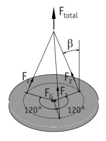
Basic Procedure
- Calculate the location of the element’s centre of gravity (MasterFrame will not provide this information).
- Set the lifting points as nodal supports on the element, and extend ‘chains’ from these supports to a location directly over the elements centre of gravity. Set each ‘chain’ member property to ignore self-weight and set appropriate releases to ensure the 'chain' member end connections remain pinned.
- Alternatively, a lifting beam or lifting frame could also be modeled.
- Decide upon a dynamic amplification factor to use for the crane lift (usually 1.2-1.5 for modern mobile cranes working inland).
- Create an ultimate load case called Dead plus Lifting and adjust the load combination to account for the lift by multiplying the partial safety factor for permanent actions by the dynamic amplification factor. You may also want to consider any temporary construction wind loads which may affect the lift.
- Run an initial analysis to find the total ultimate load of the element when lifted by the crane and apply this total load as a Y-direction force where the chains meet over the Centre of Gravity (ie. Crane Hook Node).
- The model must remain in static equilibrium at all times therefore, you may have to add additional restraints at other locations to ensure this. The subsequent examples will provide more insight on this, but the key is to ensure that no other restraints prohibit the free movement of the nodal supports under the lifting points.
- In some instances the crane hook will also need to be restrained in the x and z directions, in reality the crane rope should always remain vertical.
- Adding the chains (or lifting frame plus chains) to the analysis model allows the engineer to report the required length of each chain and the tension load acting on each chain (and if applicable, lifting frame forces). Also, if the nodal supports under the lifting points have been correctly defined, the horizontal component of the chain load will be (correctly) transferred directly to the element. For example, in the case of a truss it is vital that these horizontal components are transferred directly to the truss members, otherwise the lift analysis results would be unreliable.
Example 1 - Lifting and Asymetric Slab on 3 Points.
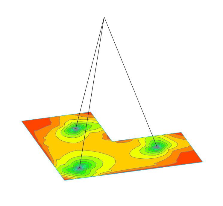
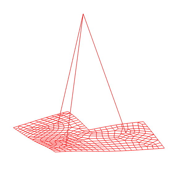
The following concrete slab is 3m x 3m x 150mm thick with one quadrant removed and will be lifted from 3 points set equal distances from the centre of gravity and at equal internal angles (120deg) from each other. When the lifting points meet both of these conditions the chains will all be of equal length, will all carry the same tension load, and the slab will remain level when lifted.
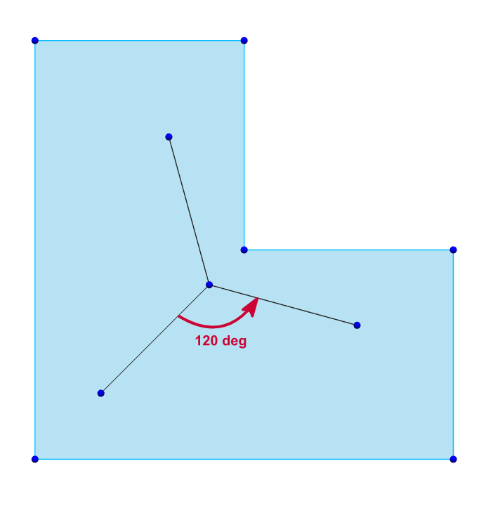
However, as long as the centre of gravity remains inside the area bounded by the lifting points and the length of the chains are set to ensure the crane hook is directly over the lifting point, the slab will remain level when lifted, but the length of the chains and the tension loads acting on the chains may not be equal.
Locate the Centre of Gravity and extend a vertical dummy member from this point to the proposed Crane Hook Node.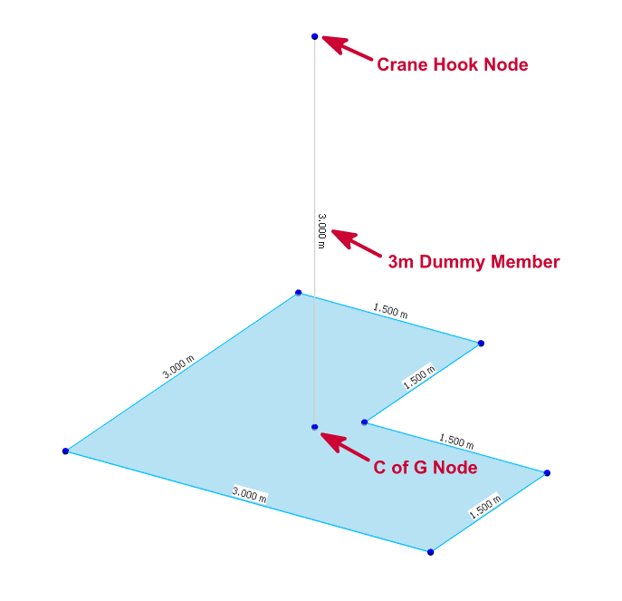
Set Lifting Points as Y-only nodal supports and extend 'chain' members to the Crane Hook Node. Set appropriate releases to ensure the 'chain' member end connections remain pinned. Apply edge restraints to the FE surface in accordance with Edge Restraints and Releases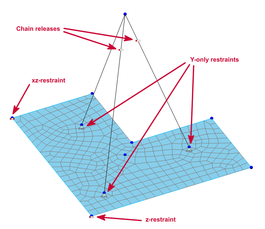
Ignore the self-weight of 'chain' members.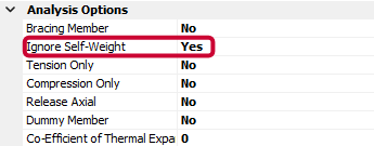
Set the load case and apply the applicable dynamic amplification factor for the crane
lift. You
may also want to consider any temporary construction wind loads which may
affect the lift.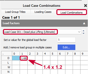
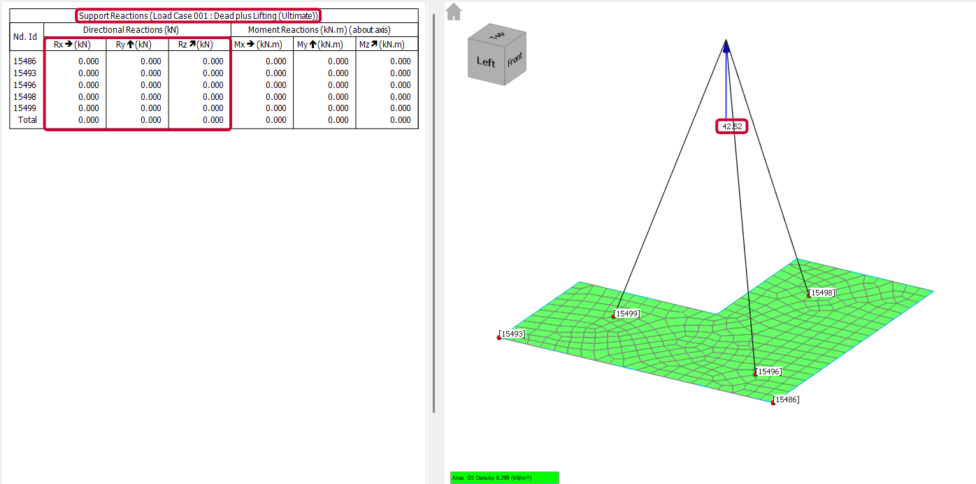
Run an initial analysis to check the total load and apply this same load (unfactored) to the Crane Hook Node.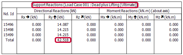
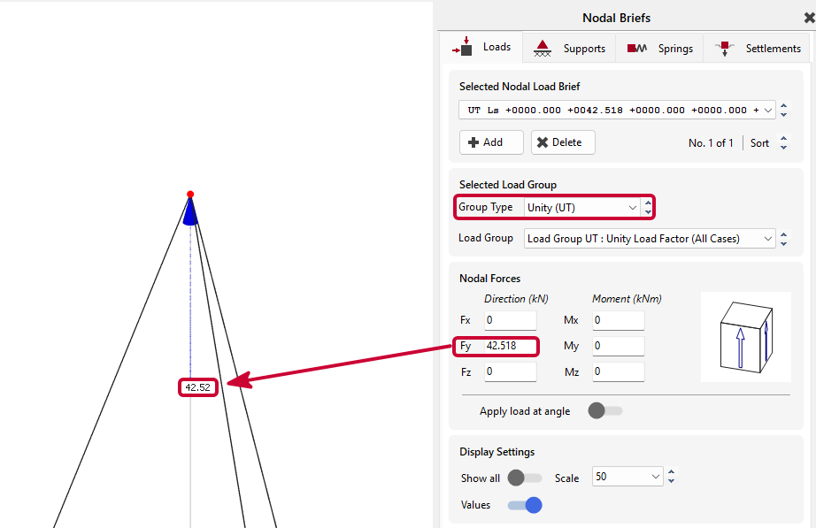
Run a second analysis and check for lift stability. If the reactions on each nodal support are zero, then the lift is stable. If not, check the locations of the nodal supports, and check that the Crane Hook Node is directly over the Centre of Gravity.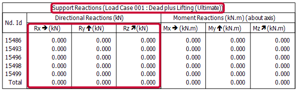
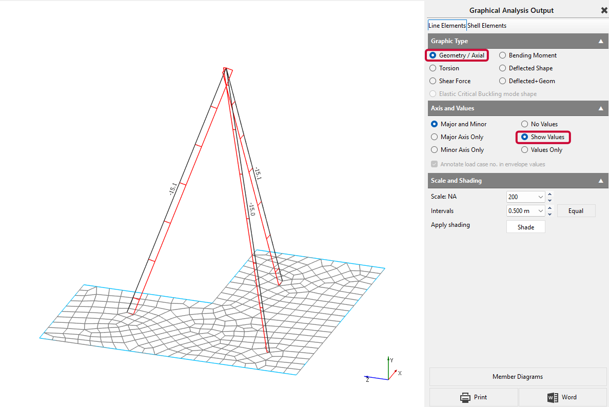
Report chain lengths, chain tension loads, and slab stresses.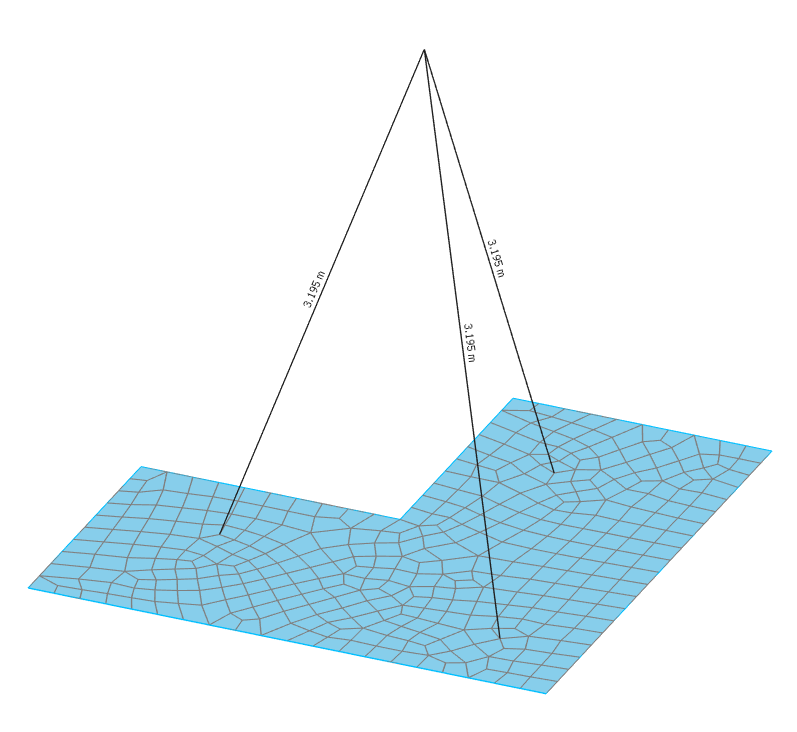
Example 2a - Pitching a Steel Truss.
The following steel truss spans 20m and weighs approx 5.5t and will be pitched from horizontal to vertical using 2 lifting points set equal distances from the centre-line of the truss (which is coincident with the Centre of Gravity). With this arrangement in place, the chains will be of equal length, will carry the same tension load, and the truss remain stable when pitched.
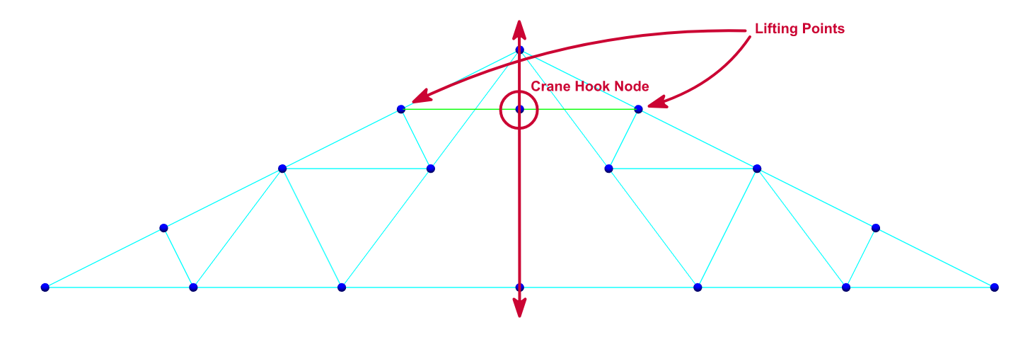
The following assessment will be carried with the truss horizontal (0 deg), you may wish to consider checking other pitching angles as the truss is pulled towards the vertical position.
Locate the line of Centre of Gravity and extend a vertical dummy member from a point on this line to the proposed Crane Hook Node.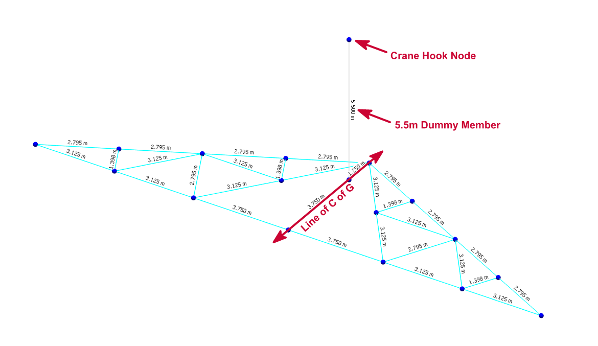
Set Lifting Points as Y-only nodal supports and extend 'chain' members to the Crane Hook Node. Set appropriate releases to ensure the 'chain' member end connections remain pinned.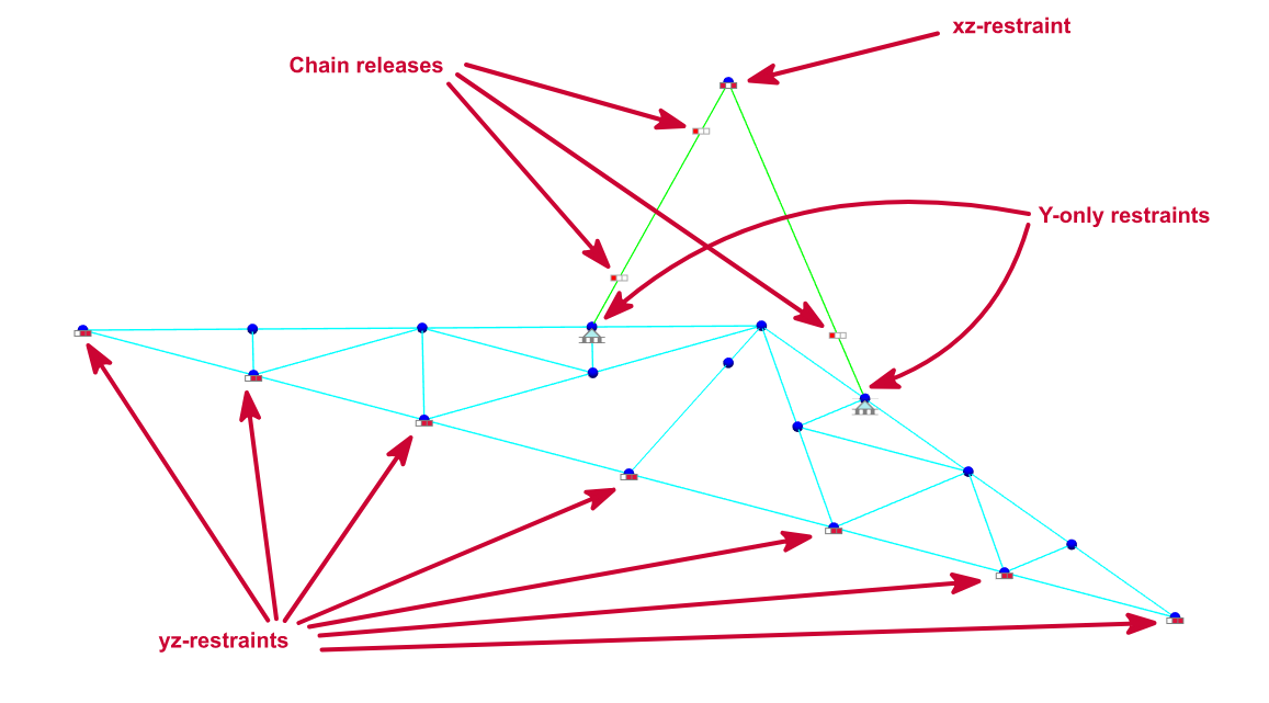
Ignore the self-weight of 'chain' members.
Set the load case and apply the applicable dynamic amplification factor for the crane
lift. You
may also want to consider any temporary construction wind loads which may
affect the lift.
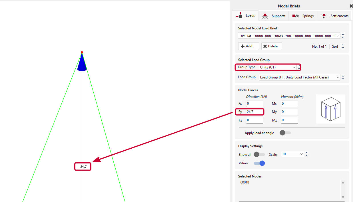
Run an initial analysis to check the pitching load and apply this same load (unfactored) to the Crane Hook Node.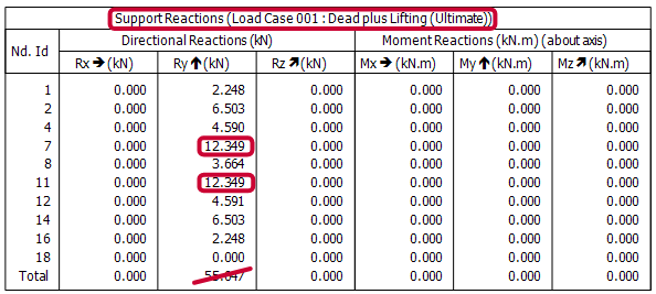
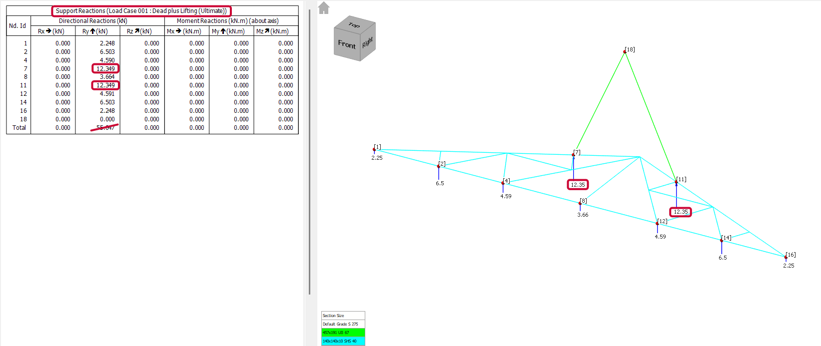
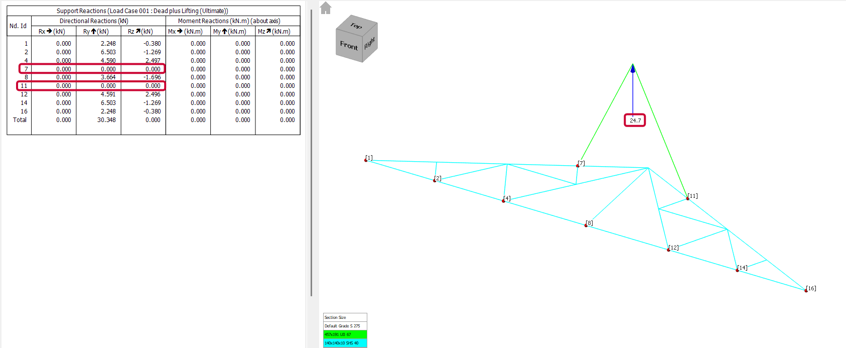
Run a second analysis and check for lift stability. If the reactions on each nodal support are zero, then the lift is stable. If not, check the locations of the nodal supports and check that the Crane Hook Node is directly over the Centre of Gravity.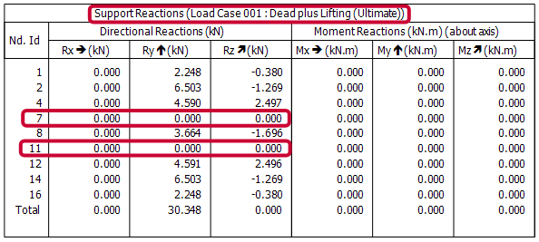
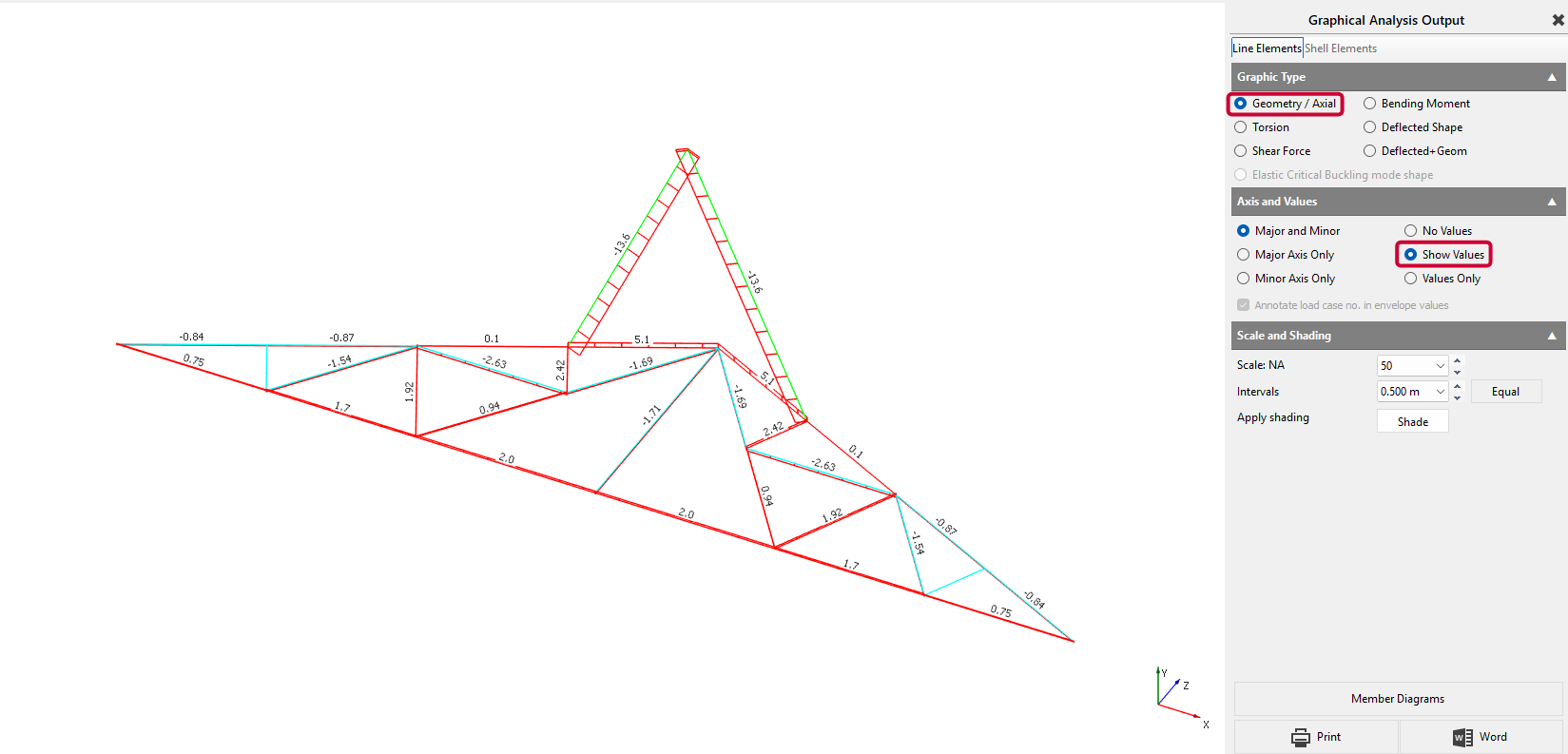
Report chain lengths, chain tension loads, and truss member forces.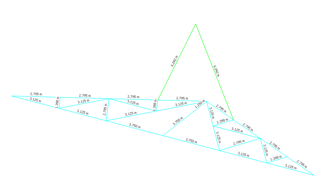
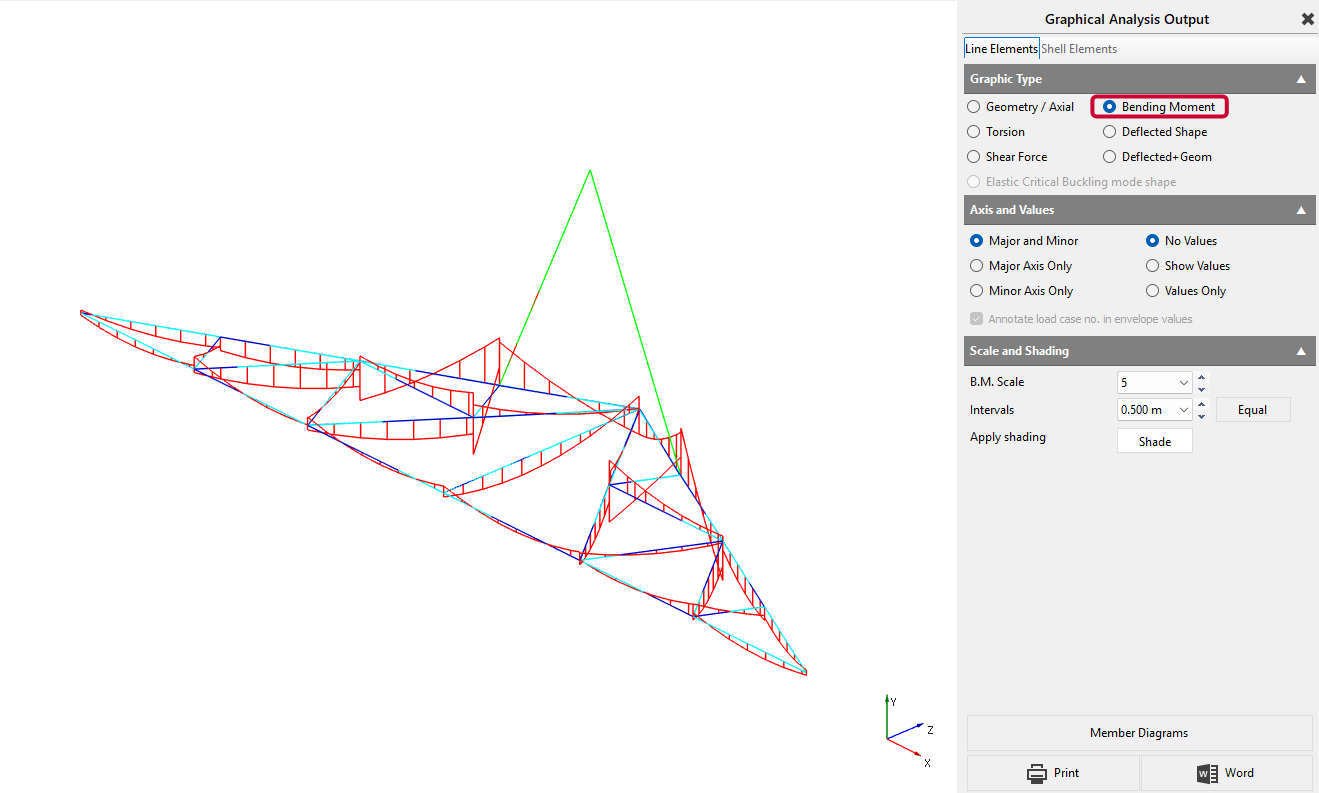
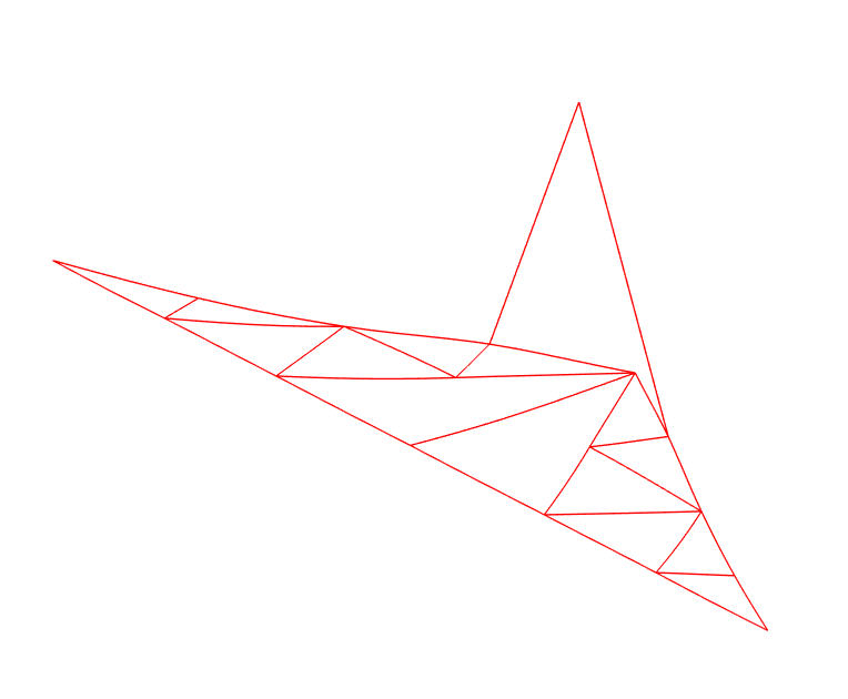
Example 2b - Lifting a Steel Truss.
The same truss which has just been pitched will now be lifted using the same 2 lifting points. Again, because the lifting points have been set at set equal distances from the centre-line of the truss (which is coincident with the Centre of Gravity), the chains will be of equal length, will carry the same tension load, and the truss will be remain level when lifted.
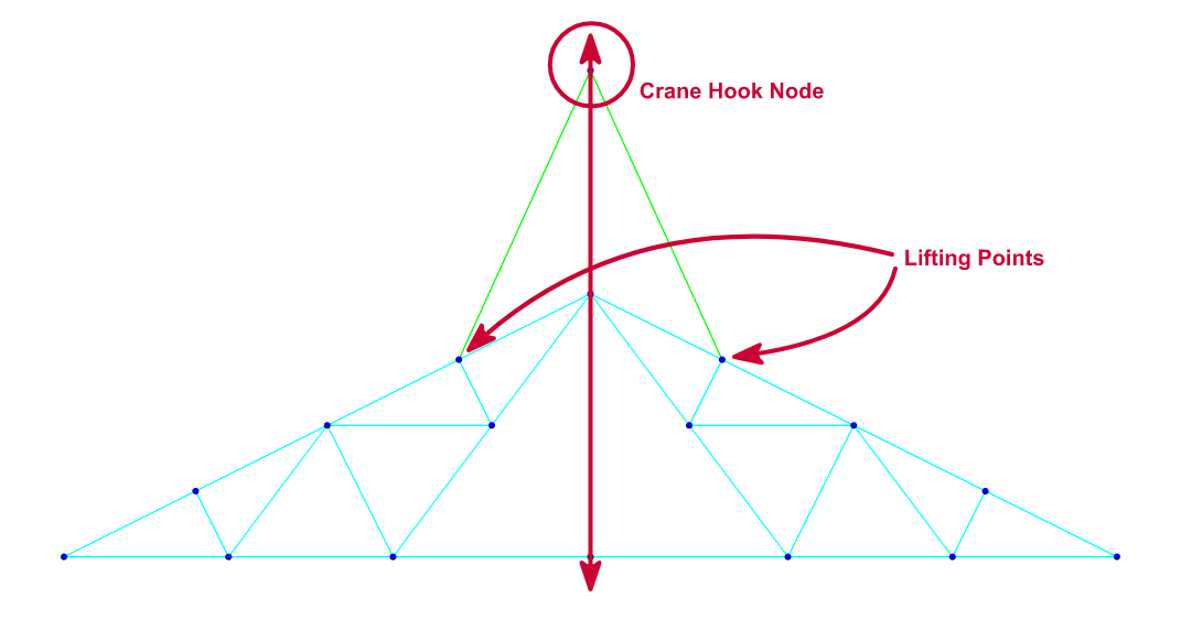
The following assessment will be carried with the truss already vertical.
Locate the line of Centre of Gravity and extend a vertical dummy member from a point on this line to the proposed Crane Hook Node.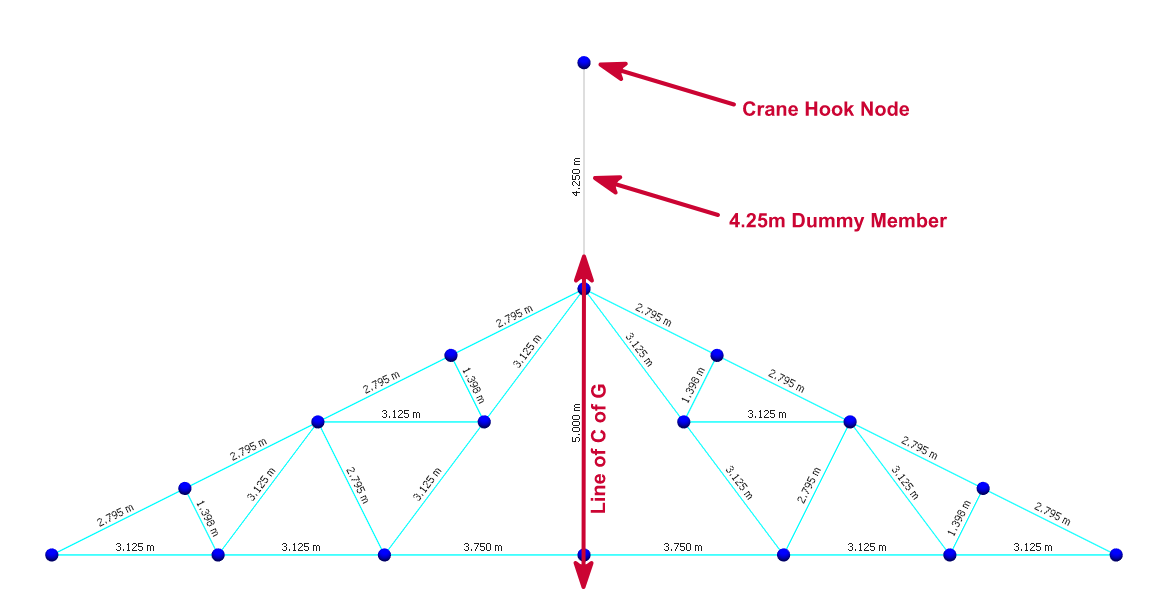
Set Lifting Points as yz-only nodal supports and extend 'chain' members to the Crane Hook Node. Set appropriate releases to ensure the 'chain' member end connections remain pinned. The z-restraints ensure that the model remains stable out-of-plane, without affecting the analysis results.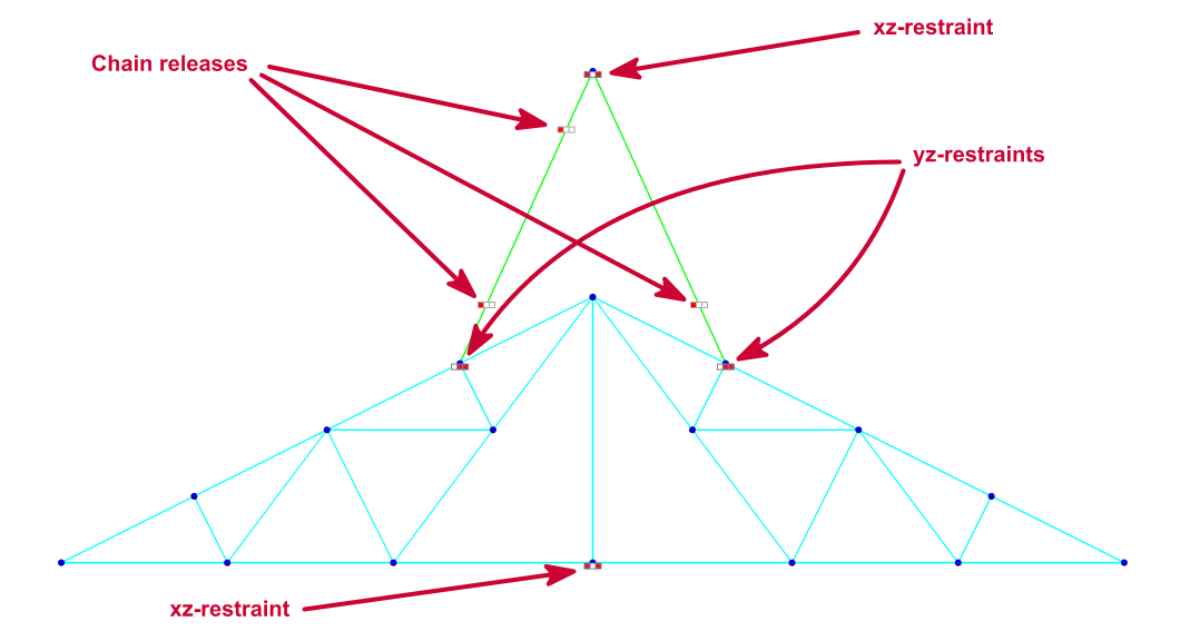
Ignore the self-weight of 'chain' members.
Set the load case and apply the applicable dynamic amplification factor for the crane
lift. You
may also want to consider any temporary construction wind loads which may
affect the lift.
Run an initial analysis to check the pitching load and apply this same load (unfactored) to the Crane Hook Node. In this case as the lifting points are the only nodes restraining the y-direction so we can safely use the total load.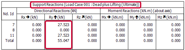
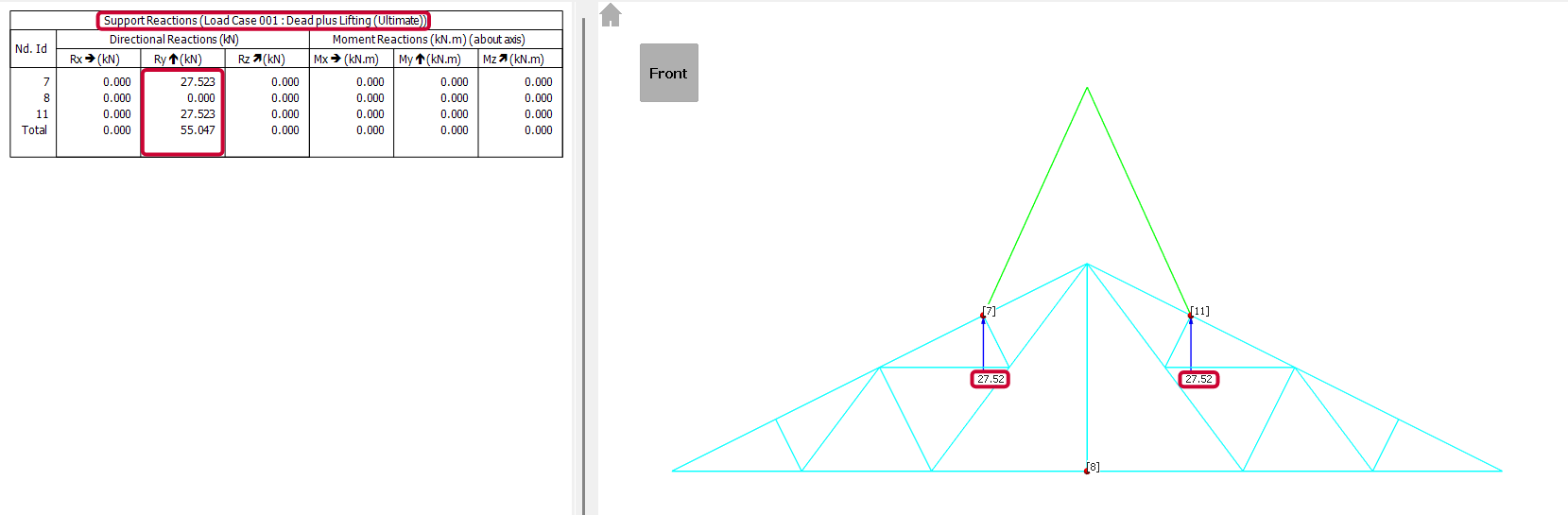
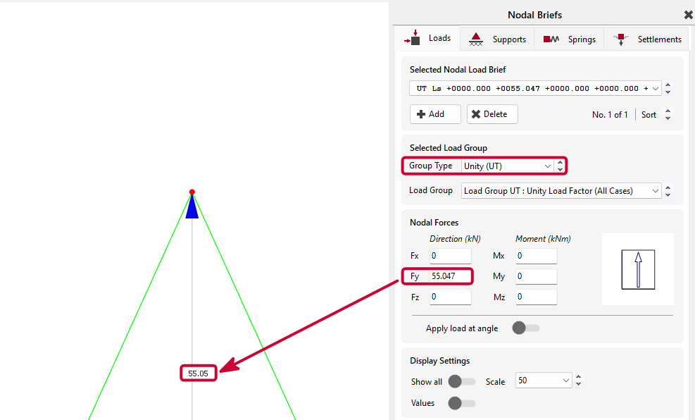
Run a second analysis and check for lift stability. If the reactions on each nodal support are zero, then the lift is stable. If not, check the locations of the nodal supports and check that the Crane Hook Node is directly over the Centre of Gravity.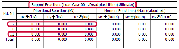
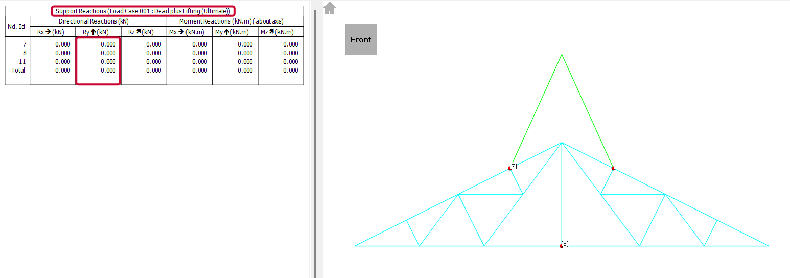
Report chain lengths, chain tension loads, and truss member forces.