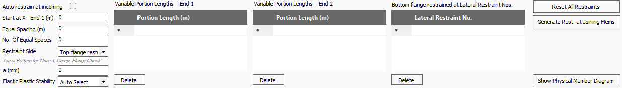
Lateral Restraints Tab
(MasterSeries 2024+)
The Lateral Restraints tab provides inputs that control restraints for lateral torsional bending design checks, primarily restraining the minor axis. The previous nine-portion restriction has been lifted, allowing you to define the number and spacing of restraints (2024+).
Auto Restrain at Incoming
Where a member has other members framing into it, for example, a primary beam supporting secondary beams, the portions can be created automatically at the position of the connecting members. This option will define a lateral restraint where another member is attached to the beam under consideration.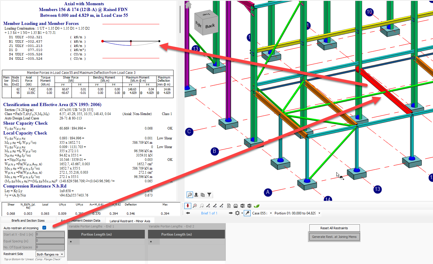
- When selected, the Portion Inputs and Generate Restraint at Joining Members options are disabled. Any amendments to the position of the incoming members in the MasterFrame model will then be automatically accounted for in the design brief on the amended members.
Portion Inputs: Defining Restraint Positions
From 2024+ Integration with Unrestrained Compression Flange Check.
The position of lateral restraints can be defined on any member using the Portion inputs. The Lateral Restraints tab now includes inputs for 'Restraint Side' and 'Restraints on other flange', which provide for top and bottom design portions. By specifying that restraints are only on the top flange, for example, the software will perform the unrestrained compression flange check on the bottom flange where it is in compression. The design checks are now sensitive to which flange is restrained, allowing the program to identify and check unrestrained compression regions based on the bending moment diagram and user-defined restraints.
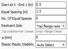
Start at X - End 1
Defines the distance to the first lateral restraint from the start of the member (lowest numbered node).
- When a Start at value is input, the portions will commence from that point. For example - when the beam is attached to the face of a deep column, the analytical node is modelled at the centreline, we could 'Start at' (depth of Column) / 2.
- Note - No design check is performed between end 1 of the member and the Start At value.
Equal Spacing (m)
Create uniformly spaced portions throughout the member
No. Of Equal Spaces
Control the max no. of restraints. If "No. Of Equal Spaces" is zero, equal spaces will fill the member length.

Variable portion length can also be entered for 1 and end 2. Variable Portion Lengths - End 1 are measured from end 1 of the member or the Start at X value if defined.
Restraint Side
You can visually confirm the top and bottom flanges of a member at any given orientation by turning on Beta Angles.
- Top Flange restrained: represented by the red cross-bar on the 'T'.
- Bottom Flange Restrained
- Both Flanges Restrained
a (mm)
The distance from the centroid of the member to the centroid of the restraint members (when top / both flange restraint selected). A value of 0.6D is used when a zero value is entered [default], where D is the parent section depth.
Elastic Plastic Stability
This relates to the type of check carried out in the unrestrained compression flange portion
- AutoSelect: the software will use the appropriate check depending on the moment capacity utilisation of the section. For class 1 or 2 section design portions where the full plastic moment capacity has been utilised a plastic stability check is carried out. In other cases an elastic stability check is performed.
- Plastic Stability: Override to force plastic stability checks. In unrestrained compression flange plastic stability checks, design requirements for buckling stability are perform using stable length calculations as per Appendix G in BS 5950 and Annex BB.3 In EC3. The section must be greater than 0.85 local capacity utilisation and be < class 3 for this override to take effect.
- Elastic Stability: Override to force elastic stability checks. In elastic design portions the buckling stability design requirements are checked using the full calculation for axial torsional buckling and lateral torsional buckling, with appropriate interaction formula used. E.g. in EC3 NEd/NbRd + kzy*MEd/Mbrd < = 1.0.
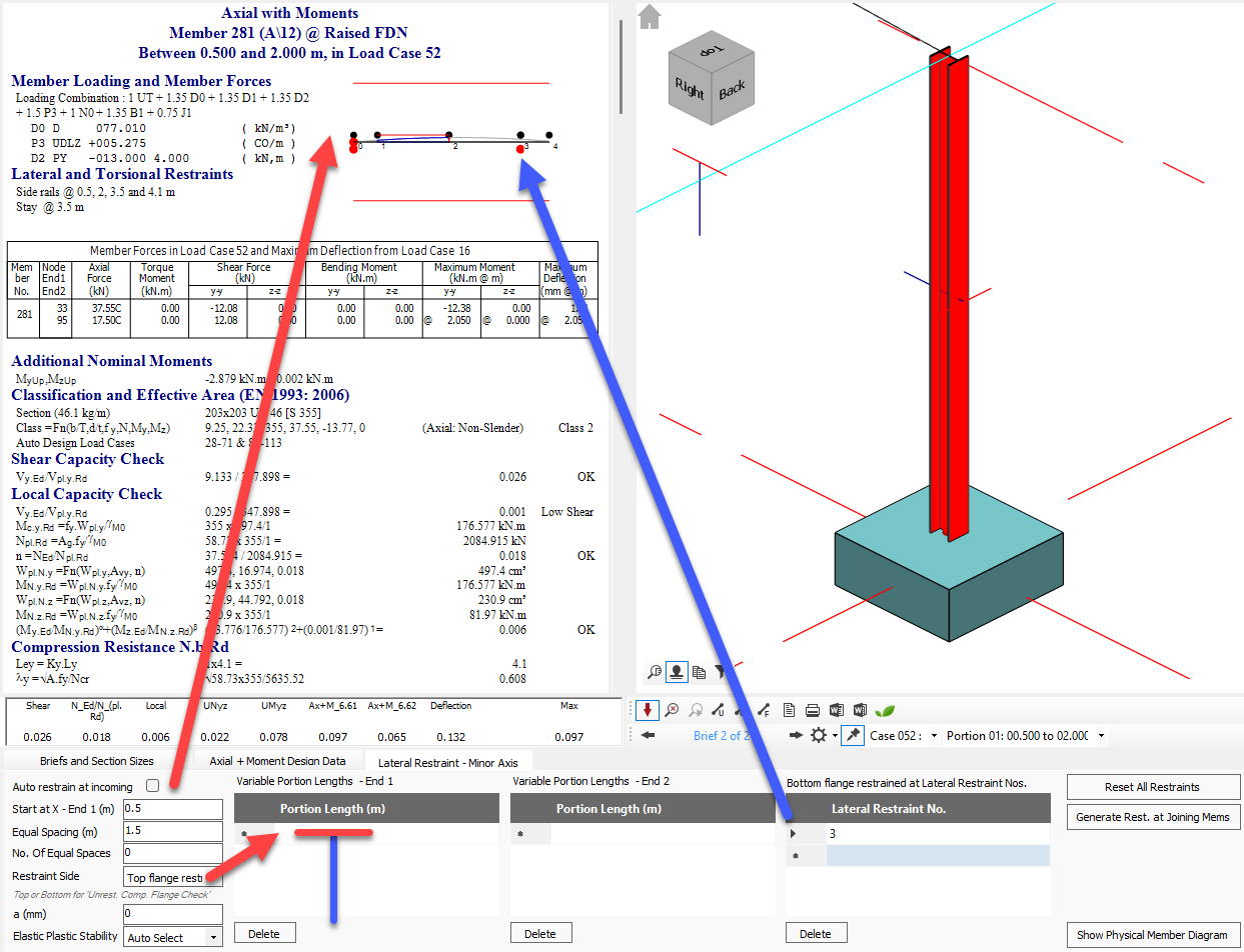
Other Side Flange Lateral Restraint Positions (Stays)
- Lateral Restraint No.: Flange restraint to the opposite flange i.e. stays. This input is not a distance but the lateral restraint number as annotated in the design output. This is 'other side' flange restrain is coincident with the lateral restraint.
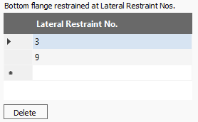
Reference to the restraint number can be seen on the local moment capacity diagram on the calculation pane .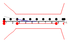
By specifying that restraints are only on the top flange, for example, the software will perform the unrestrained compression flange check on the bottom flange where it is in compression. Hence the 'other side' flange lateral restraints (stays) control the unrestrained compression flange design check portion lengths. The design checks are now sensitive to which flange is restrained, allowing the program to identify and check unrestrained compression regions based on the bending moment diagram and user-defined restraints.
The design buckling length of the unrestrained compression flange length is controlled by the position of the stays and also the bending moment diagram. In the above example we have an equal spacing of 1.4m. With stays at lateral restraint numbers 3 and 9, the bottom flange design portion length is 8.4m. However, compression only exists in the bottom flange up to 2.6m (just before lateral restraint no. 5). In this case the design portion buckling length will be
- Eurocode - the buckling length is taken up to the next lateral restraint number beyond the point of contraflexure, i.e. 2.8m.
- BS design - a global design option exists to take the buckling length to the point of contraflexure at 2.6m, otherwise it is taken as 2.8m as per Eurocode.
Viewing and Selecting Portions
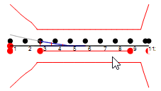
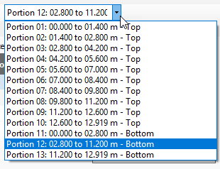
Portion positions are indicated in the results local moment capacity diagram. The portions can be checked and selected
- Graphically: by clicking on the portion length within the diagram
- Drop-down menu: Select the relevant "Portion"
Reset All Restraints
Automatically resets all values to zero.
Generate Restraint at Joining Members
Will automatically input the Portion lengths in the End 1 grid. Allows for further manual amendments for your Portion inputs.

Auto Restrain Current Group (MasterPort Only)
Automatically generates restraints.
Show Physical Member Diagram
This produces a member detailing dimensioned representation of the lateral restraint and stay locations. The annotated diagram below demonstrated the Start At, Variable Portions 1, Equal Spacing, Variable Portion 2, Make up end 2 portion restraint layout.
