Applying Local Bow Imperfection in MasterSeries 2025
Introduction – Local Bow Imperfections in MasterSeries
In real structures, compression members are never perfectly straight. Small initial out-of-straightness (known as local bow imperfections) can significantly influence the buckling behaviour of slender members under axial load.
In Eurocode design, these imperfections are typically accounted for implicitly through the use of buckling curves and reduction factors in Clause 6.3 of EN 1993-1-1. Alternatively, the code allows imperfections to be considered explicitly at the analysis stage by introducing a small initial member curvature and carrying out a second-order (geometric non-linear) analysis.
When Local Bow Imperfections are enabled in MasterSeries, the software follows this second approach. A small geometric imperfection is applied to the member and the resulting second-order effects are captured during analysis. This allows the buckling behaviour of the member to be represented directly in the structural analysis rather than relying solely on the implicit buckling curve method at the design stage.
Local Bow analysis benefits Structural Design Engineers by providing:
A more realistic second-order simulation of local member instability
Better accuracy for slender or heavily-axially loaded members
Improved insight into how axial load amplifies imperfections
Safer, clearer identification of critical members
A modern analysis capability that complements EC3 buckling curves rather than replacing them
It bridges the gap between conventional code-based design and advanced geometric-nonlinear analysis, giving engineers a more robust and reliable assessment of member stability, especially in cases where traditional buckling curves may not fully reflect the member’s behaviour.
This is an approach that accounts for in-member geometric non-linearity, also known as small P-delta effects. Here is a guide on when and how to apply it.
When to Apply Local Bow Imperfection Loading
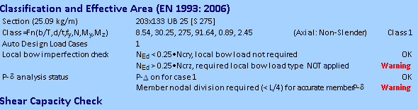
The application of local bow imperfection loading is required when the applied axial force (NEd) is greater than 25% of the member's elastic critical buckling load (Ncr).
Note the 0.25 * Ncr is rearrangement of EN 1993-1-1:2005 eqn 5.8, but is also how this presented in EN 1993-1-1:2022.
- In MasterKey Steel design - Axial+ Moment Design brief, this check is performed for both the major and minor axes of the member.
- A warning will be issued if this condition is met but the local bow imperfection loads have not been applied. For instance, the software might indicate that for the minor axis, NEd is greater than 0.25 * Ncr, and warn that local bow loads haven't been applied.
- Note that in steel design the Ncr values for major and minor axis for this check use the unfactored length (hinged ends) as per EN 1993-1-1:2005 5.3.2 (6).
- The Ncry (major axis) is based on the member length or the Ly manual input in design brief if specified.
- The Ncrz (minor axis) is based on the laterally restrained portion length or the Lz manual input in the design brief if specified.
The engineer should ensure the appropriate lengths are being used before taking further action to implement local bow imperfection loads + P-Delta analysis.
When not to Apply Local Bow Imperfection Loading
Under EC3, column imperfections can be allowed for either by using the buckling curve approach in Clause 6.3 (via χ-reduction factors and interaction equations), or by explicitly modelling member imperfections within a second-order analysis in accordance with Clauses 5.2.2 and 5.3.2 (formalised as Method M4 in EN 1993-1-1:2022). The NSC guidance emphasises that engineers should avoid double-counting in-plane buckling effects by combining both approaches for the same buckling mode. Nominal column moments are another imperfection proxy and, where Local Bow and P-Δ analysis are already included, their use may be conservative and should be applied deliberately.
Where Local Bow imperfections are included via second-order analysis (Method 4), the traditional in-plane flexural buckling interaction checks should not be used again to represent the same behaviour. However, compression resistance checks remain necessary to verify torsional, torsional-flexural, and lateral-torsional buckling, as these are not captured by local bow imperfections. The same principle applies when minor-axis local bow is included for minor-axis flexural buckling, although current guidance is less explicit and some conservatism may remain in practice.
This doubling up does not occur in the major axis, as design adjustments are made. Only the overall member analysis ends moment are assessed for local bow qualification. Where no end moment exists, local bow is not required.
What is 'Local Bow' designing for
Member axial flexural bucking is normally empirically designed for using member buckling reduction factors in the design code in EN 1993-1-1:2005 6.3.1. The 'Local Bow' check is an second-order P-delta analytical approach to capturing this buckling behaviour in more heavily axially loaded and more slender members. By subdividing the member with internal nodes and by apply the local bow load in induce geometric imperfection, the second-order P-Delta analysis can capture the local member geometric non-linearity in a more sophisticated fashion at analysis time.
How does the design approach change?
When local bow imperfection is required and applied, this means the member flexural buckling in accounted for at design time. Hence in accordance with EN1993-1-1:2005 5.2.2. (3) & (7), the flexural buckling check in 6.3.1.1 do not need to be applied. The following changes are made to the final axially load + moment interaction buckling equations.
- Equation EN1993-1-1:2005 6.61 is omitted. This is more explicitly stated in 2nd generation EN1993-1-1:2022 7.2.2 (7b) M4 analysis method.
- In Equation EN1993-1-1:2005 6.62 the χz flexural axial buckling reduction factor is taken as 1.0. χt (axial torsional buckling) and where relevant χtf (axial torsional flexural buckling) is used in place of χz in equation 6.62.
How to Apply the Local Bow Imperfection Attribute
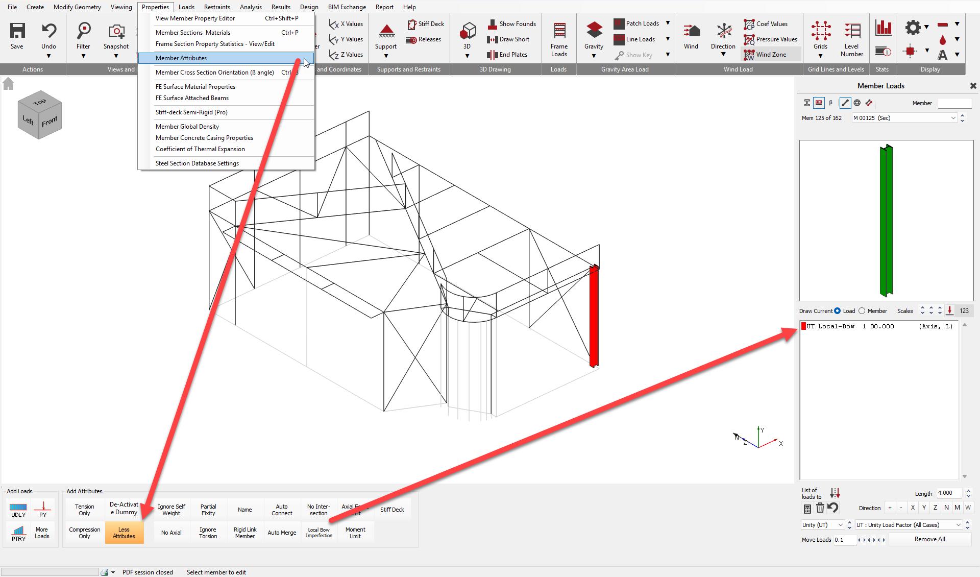
You can apply the local bow imperfection loading by assigning the 'Local-Bow' member attribute in the software.
This can be found within Properties -> Member Attributes and under 'More Attributes'. Entry settings can be found within the📄 Member Attributes manual entry.
In Summary
- Perform the Steel Design Axial +Moment members checks and examine the Local bow imperfection check results
- In MasterFrame, apply the 'Local-Bow' attribute for the required axis.
- Ensure analytical subdivision is in place, for example, by using 'Model Auto-Connect', which may also be automatic.
- Activate P-Delta analysis for the load cases where the NEd > 0.25 * Ncr condition is met.
Be aware that applying these loads and running a second-order analysis will introduce additional forces and moments, which might cause a previously passing member to fail. In many cases, engineers might prefer to increase the section size to avoid this complex analysis.