
Wind Directions Settings (and Cpi Values)
Turn on 'Use MasterKey Wind Loading' to activate the options within this menu.
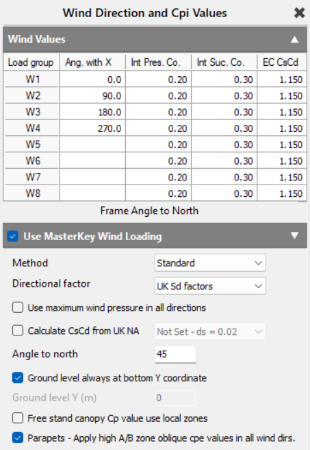
Angle with X (Wind Directions)
Up to 8 wind directions on the frame can be considered using the load groups W1 to W8. The direction of the wind is defined based on the angle with the frame’s global X axis. For example W1 to W4 could be used to define four principal wind directions, 0, 90, 180 and 270 degs for a rectangular shaped building. The angle between the frame Z axis and magnetic North is specified in the ‘Angle to North’ text box. If the 'Draw Global Axis’ (📄 The Display toolbar) icon is on, then the global axis symbol at the bottom right of the screen graphically indicates the North direction in relation to the frame global axis.
Internal Pressure and Suction Co-efficient Values
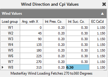
Wind Methods and Directional Settings
There are several wind methods available in the design codes. The particular method you wish to use can be selected in the ‘Method’ box.

Method
- Standard:
User Defined: In selecting this option, a table opens up to enable you to enter your User Defined Values for the site. These will be used as the dynamic wind pressures for the various heights of your building. Note that the dynamic wind pressure ‘q’ is entered in units of Newtons per metre squared (N/m2), not kN/m2 as would often be the case. This is so the values line up with those used internally within the site data module. Wind reduction factors can be added for various wind diagonal lengths.
.png)
Directional Factor
- UK Sd factors:
- Sd factors = 1:
Use maximum wind pressure in all directions
Takes the maximum pressure and applies it in each direction. This is useful if you do not know the orientation of the building at a preliminary design stage.
Augmentation Factor, Cr (BS Only)
BS 6399-1, 1.6 discussed Dynamic Classification. It allow you easily determine a Cr augmentation factor to account for dynamic effects. This is determines form figure 3 for a given height and type of building. The Cr is not determined automatically by MasterSeries and must be manually entered, however a conservate maximum default value of 0.25 is taken. For many low-rise stand steel and concrete structures this value can reduce to much nearer 0, hence it is highly beneficial to adopt a more specific value. The Cr is applied as an wind pressure augmentation factor of (1 + Cr) as per 2.1.3.6 eqn (7). The Cr value applies to Overall Wind Load cases only . See 📄 Final Wind Pressure Calculation
Calculate CsCd from UK NA (EC Only)

Determination of Cs and Cd factors for wind
The structural factor CsCd takes into account the effect on wind actions from the non-simultaneous occurrence of peak wind pressures on the surface (Cs) together with the effect of the vibrations of the structure due to turbulence (Cd). For further detailed information see section 6 of EC1-1-4 and associated National Annex.
In the wind loading input area the CsCd factor can be directly entered by the user or, alternatively, the program can evaluate the CsCd factor based on the building type. Select the type of building from the droplist in the MasterKey Wind Loading panel. The program will calculate the CsCd based on the UK NA.
The CsCd value applies to Overall Wind Load cases only . See 📄 Final Wind Pressure Calculation

MasterKey Wind Site Ground Level in MasterFrame Coordinate Space
Wind site pressure is evaluated for various heights of the building above the wind site ground level. The wind site ground level relative to the MasterFrame coordinate can be be controlled with the following two inputs. In this way the MasterFrame Y coordinates used can be independent of the actual height of the building above ground and any model Y coordinate reference system can be used.
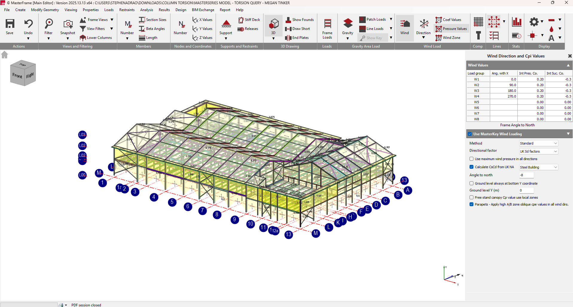
In effect the wind site building heights are then z(e) = Model Y value - Ground level Y value.
Ground Level always at bottom Y Co-ordinate
With this box checked, the wind site ground level will be at the minimum model Y coordinate.
Ground Level Y (m)
With above box unchecked you can freely enter a ground level Y coordinate in the MasterFrame coordinate space.
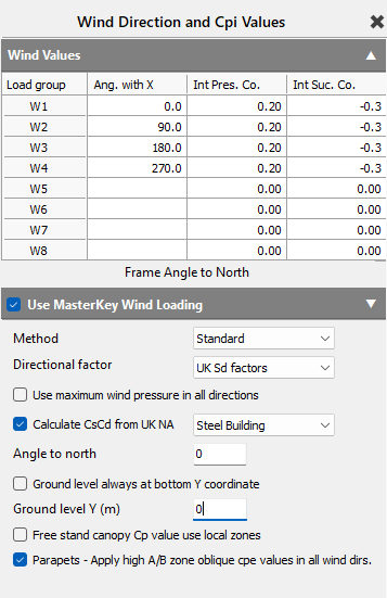
Free Stand Canopy Cp Value use local wind zones
The application of of wind pressure coefficient values for free standing canopies(Cp) is covered by BS 6399-2, 2.5.9.1. Tables 13 and 14 give 'Overall coefficients' and 'Local coefficients'. The use of these values is discussed in 2.5.9.1.3 and 2.9.5.1.4, however local values should be used for the canopy member design, and overall values used for the design of the canopy supporting members.
Parapets - Apply high A/B Zone Oblique Cpe Values in all Wind Directions
The application of of wind pressure coefficient values for parapets (Cp) is covered in BS 6399-2, 2.8.1. Clause 2.8.1.2 discusses the application of the higher wind zones A & B for wind direction where wind is applied at 45degrees (oblique) at the end of the parapet. As a conservative simplification and to avoid having to apply these specific wind directions, the higher A&B wind zones can be applies in all wind directions.
Check this option to apply high A / B zones to all wind angles and not just 45 degree oblique angles as per BS 6399-2, 2.8.1.2.