
Wind Load Reduction Members (Wind Diagonals)
See also 📄 Understanding Wind Diagonals (Wind Load Reduction Members) in MasterSeries
Eurocodes
In EuroCode wind design, individual members can be specified for local or overall wind effects. (Wind diagonals are only relevant in British Standard design and have a similar function).
This option has the effect of designing the members which are locally loaded by wind (such as cladding members) for a larger wind pressure than members which are globally loaded by wind, e.g. vertical bracing members.
By default it is assumed that all frame members are being designed for local wind effects. If there are members in your frame that you want to be only considered for overall wind, eg, bracing members, you can place these members in the Wind Load Reduction groups.
Select ‘Wind load reduction on globally wind loaded members’.
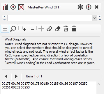
On the frame, click on the members on which the wind load reduction will apply.
British Standards
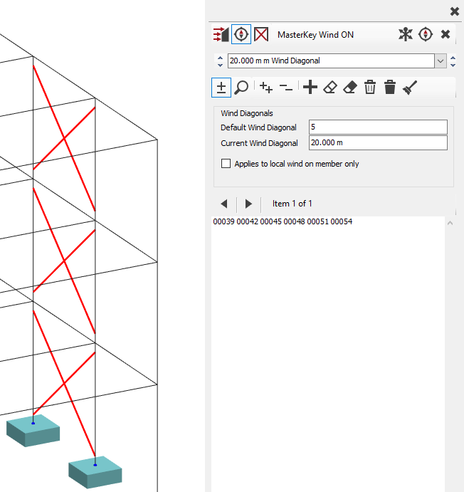
Default Wind Diagonal
Current Wind Diagonal
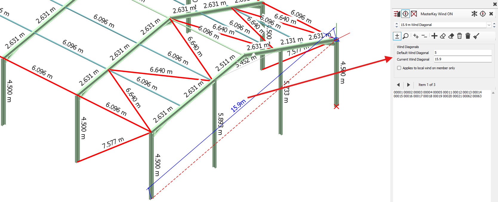
In BS design the wind diagonals are picked from the frame and given a wind diagonal dimension - this value can be an average dimension to cover a number of elevation diagonal lengths. It works in a similar way to the EC method above.
The “a” value is: not the physical member length itself, but rather: the representative size of the wind-loaded structural system contributing to the bracing force.
Applies to local wind on member only
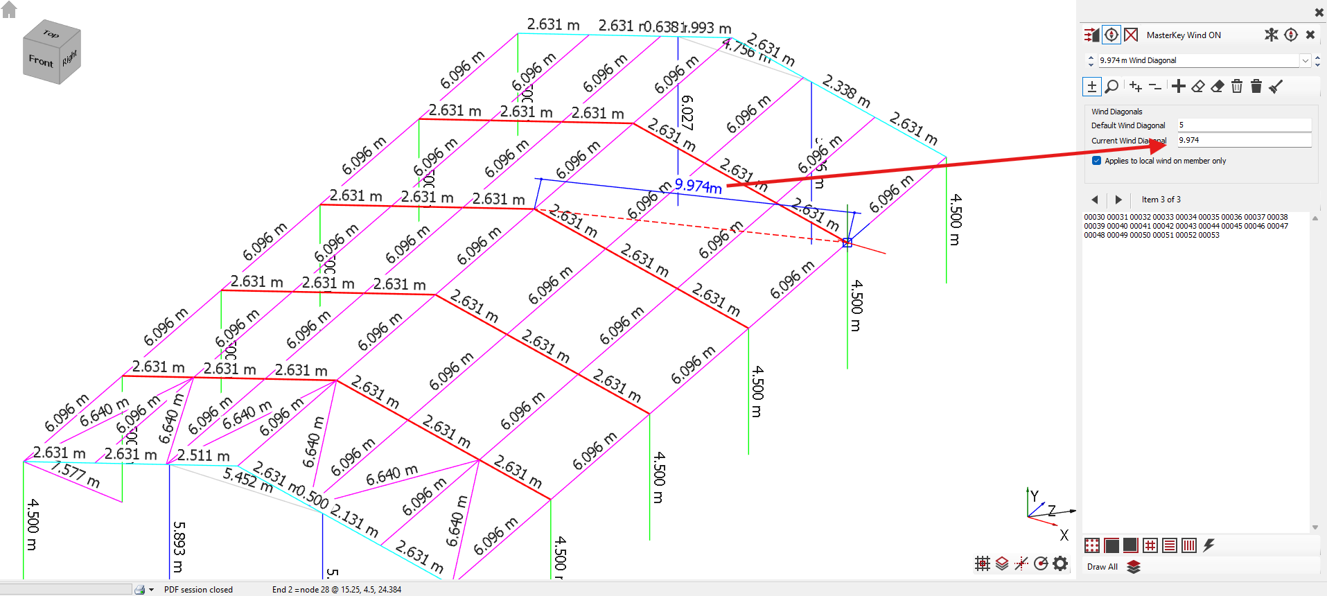
Wind reduction factors can also be applied to the local wind on selected members which take wind from a large area, for example, portal rafter members where the wind area could be (say) 20m long by 7m wide giving a local ‘a’ diagonal value of 21.2m, rather than the default value of 5m.
Load Case Generation and Wind Diagonals
Load Case Generation and Wind Diagonals
Load cases may need to be regenerated after changes are made to the wind diagonal settings.
The standard W, P and S load cases are generated using the default wind diagonal length (typically 5 m) and represent the local wind effects. These cases will generally govern the design of locally wind-loaded members such as purlins, rails, cladding supports and gable posts. In these members, the wind effects are primarily influenced by the local wind pressure acting directly on the member and its tributary area.
Additional wind diagonal groups may be defined with larger diagonal lengths representing the size of the overall structural wind system (for example braced bays or portal frame systems). When these are defined, the software generates additional W load cases for the larger diagonal values, intended for globally loaded members such as vertical bracing, roof bracing and tie systems. These overall wind cases apply statistical size reduction, recognising that peak local wind pressures are unlikely to occur simultaneously over the entire structural system. Internal pressure and suction effects are not considered for these overall stability cases, and therefore additional P and S cases are not generated. Members such as portal rafters and columns may fall between purely local and purely global behaviour, and the engineer may choose to apply a local member wind diagonal reduction using the “Applies to local wind on member only” option where appropriate.
Read more 📄 Understanding Wind Diagonals (Wind Load Reduction Members) in MasterSeries