
Load / Cpe Tab
Funnelling and Blockage
The wind zones, coefficients of pressure and dynamic wind pressures are automatically calculated within the wind analysis module when the panels are applied to the envelope of the building. Therefore the Load/Cpe table will remain blank.

Overriding Cpe Values
You can override the automatically calculated values, if required, by typing in your own values for any of the Cpes, zones, funnelling effects and angles between surfaces (beta angle).
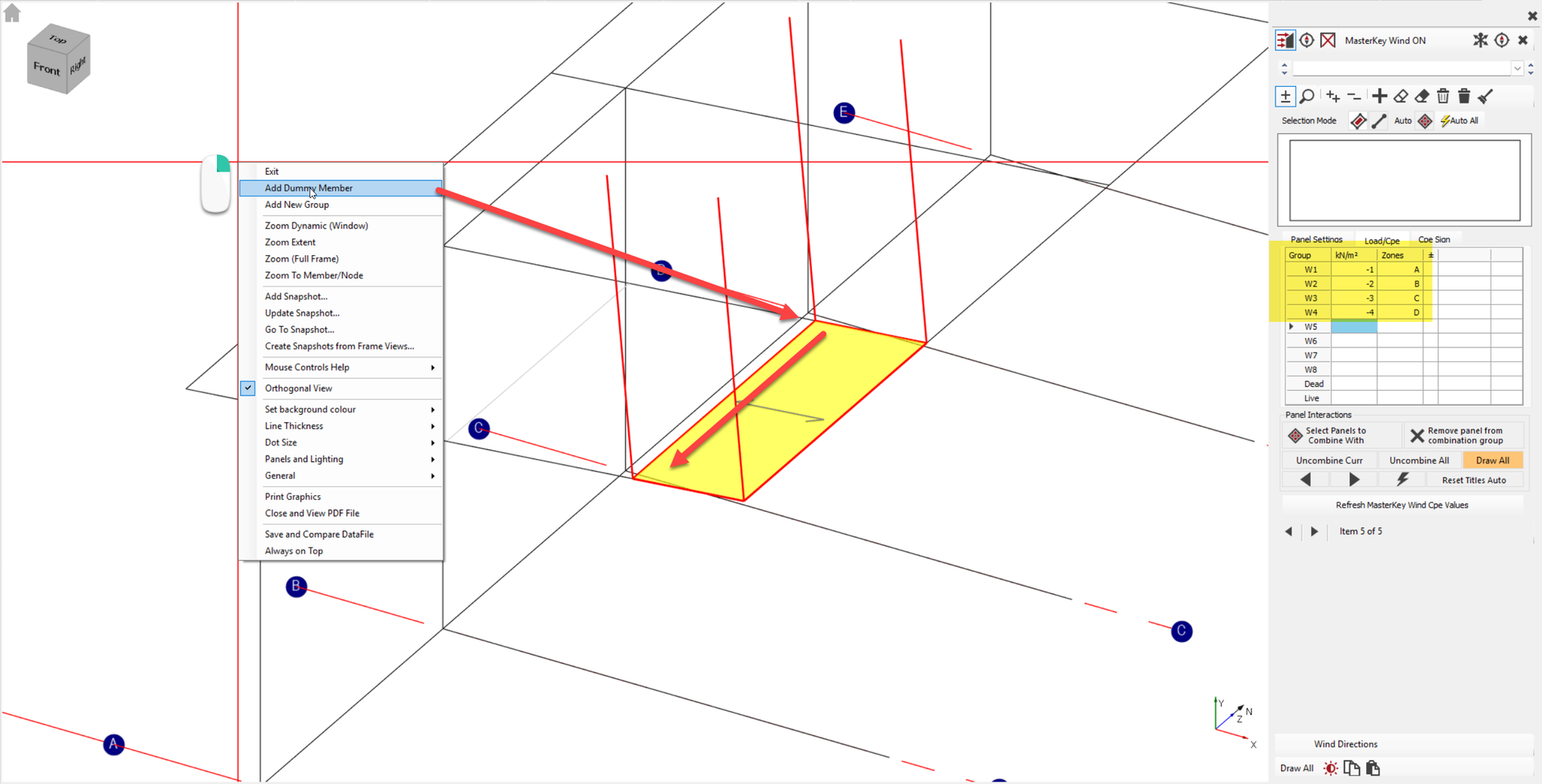
This coefficient value applies to the selected panels so you will likely have to split you structure down into smaller 'sub panels' to give the desired resolution for the Cpe coefficients for the different 'zones'. You can define sub-panels by Right Clicking the mouse button and selecting 'Add Dummy Member'.
These coefficients will work with the MasterKey site data.
Overriding kN/m2 Values
This can be done by turning off the Use Wind Loading option within the Wind Directions and Settings.
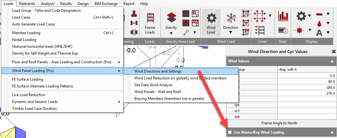
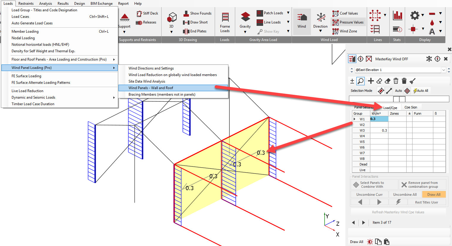
This will allow you to specify a kN/m2 value within the Loads Cpe Tab within the Wind Panels menu.
Read more here: 📄 Create Your Own Site Data
Funnelling
See also 📄 Using the Funnelling Input in MasterSeries
Funnelling occurs when two buildings face each other and the wind is forced through the gap between them. This accelerates the airflow, making the external pressure coefficients Cpe more negative (higher suction) than for an isolated building.
This effect is described in BS 6399-2, Clause 2.4.1.4 (also see Clause 3.3.1.1.3 and Figure 12).
Funnelling occurs when the gap width between two opposing façades lies between:

where b is the building breadth perpendicular to the wind direction.
If the gap is less than b/4 or greater than b, treat the building as isolated (no funnelling effect).
How to enter funnelling in MasterSeries
In the “Funn” column, enter a ratio between 0.25 and 1.0:


Change the funn value and click 'Refresh MasterKey Wind Cpe Values'.

0.25 corresponds to a gap of b/4 (onset of funnelling).
1.0 corresponds to a gap of b (no funnelling).
The maximum suction effect occurs at a funnelling ratio of 0.5 (gap = b/2).
How MasterSeries calculates funnelling
- The software uses BS 6399-2, Table 5 to determine modified cpe values for zones A, B, and C on the windward walls.
The input ratio (0.25–1.0) tells the software where your gap lies in relation to b.
MasterSeries then:
Applies the appropriate funelling coefficient from Table 5.
Interpolates between values when necessary (e.g. for intermediate D/H ratios, as per the note at the foot of Table 5).
Important notes
- The funnelling ratio can be different for each wind direction, because the building breadth b changes depending on the face the wind is acting on.
Always check the geometry carefully for each wind case before entering a ratio.
If the structure is not within the funnelling gap limits (<b/4 or >b), enter no value (or 1.0) → building treated as isolated.
In summary:
Input = gap / building breadth b.
Valid range: 0.25 ≤ Funn ≤ 1.0.
Maximum effect = 0.5.
MasterSeries applies BS 6399-2, Table 5 with interpolation to compute adjusted cpe.
Zones
In MasterSeries, wind panels represent areas of a building envelope (walls or roofs) that are subjected to wind loading.
Because wind pressure varies across a surface, panels are divided into zones. Each zone is assigned an External Pressure Coefficient (cₚₑ) which represents the level of wind pressure or suction acting on that area.
These zones follow the rules defined in BS EN 1991-1-4 and BS 6399.
Why Zoning is Used
Wind pressure is not uniform across a building.
Corners and edges experience the highest suction.
Central areas experience lower pressures.
Windward faces experience positive pressure.
Dividing surfaces into zones allows the software to apply different pressure coefficients where needed, giving a more realistic representation of wind loading.
Typical Zone Types
Walls
Walls are commonly divided into:
Zone A & B – Corner and edge regions (high suction)
Zone C – Central wall area
Zone D – Windward pressure zone
Flat Roofs
Flat roofs are typically divided into:
Zone F – Corners
Zone G – Edge strips
Zone H – Intermediate areas
Zone I – Central roof
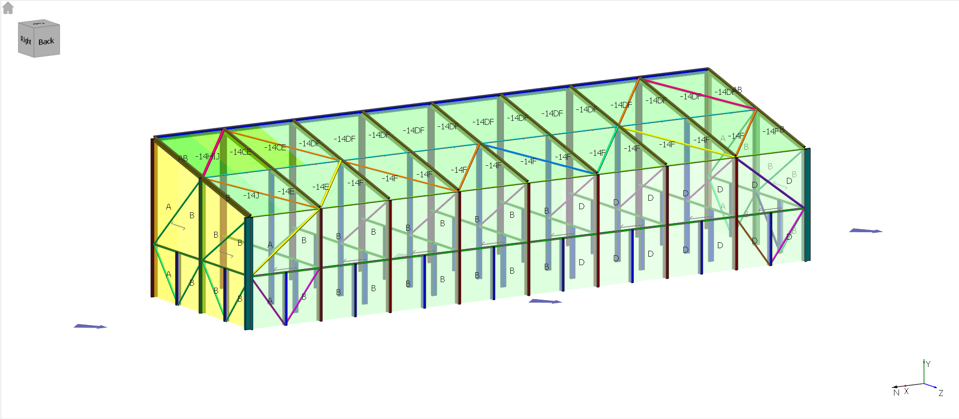
Pitched Roofs
Pitched roofs have additional zones (often F–J or K–S) depending on roof pitch and wind direction.
How MasterSeries Calculates Zones
MasterSeries automatically determines zoning by analysing the building shape and wind direction.
The program:
Identifies the leading wind edge
Measures distances across the surface to determine zone boundaries
Applies the correct pressure coefficients
If a wind panel overlaps multiple zones, the software calculates a weighted average coefficient based on the area of the panel in each zone.
Adjusting Zones for Complex Buildings
Inset Storeys
For stepped or set-back buildings, split wind panels at each level so the program recognises a new leading edge.
Dummy Members
Dummy members can be added to break large panels into smaller ones, allowing more accurate zoning (useful for cladding checks).
Panel Combination
Panels that form one continuous surface can be combined so zoning is applied across the entire wall rather than restarting on each facet.
Checking the Zones
Wind zones can be viewed in the model by enabling Wind Zone Labels.
The display uses colours to show pressure and suction areas, helping you confirm that edges, corners and windward faces are correctly identified for each wind direction.
Blockage
Blockage describes how much airflow is obstructed beneath a canopy or freestanding roof without permanent walls.
The amount of obstruction affects the pressure that builds up beneath the canopy, which influences the net wind uplift acting on the roof.
This effect is represented by the blockage ratio (ϕ).
Blockage Ratio (ϕ)
The blockage ratio ranges from 0 to 1.
| Value | Description |
| ϕ = 0 | Empty canopy – wind can pass freely underneath |
| 0 < ϕ < 1 | Partially obstructed canopy |
| ϕ = 1 | Fully blocked canopy – contents block airflow up to the downwind eaves |
A higher blockage ratio generally increases uplift on the roof.
How Blockage is Calculated
Blockage is normally calculated as:
ϕ= Obstructed Area beneath Canopy / Total Area beneath Canopy
Areas should be measured normal to the wind direction.
In simplified cases it may also be approximated as:
ϕ= Height of Obstruction / Minimum Canopy Height
Effect on Wind Coefficients
Design standards provide coefficients for:
ϕ = 0 (empty canopy)
ϕ = 1 (fully blocked canopy)
For intermediate values, the coefficients are linearly interpolated.
According to design codes:
Increased pressure from blockage is applied upwind of the obstruction
Downwind areas use coefficients for an empty canopy (ϕ = 0)
Using Blockage in MasterSeries
When generating wind panels for canopies:
Enter the blockage ratio in the Wind Panel Generation settings
Example: 0.85 = 85% blockage
For connected canopy roofs, the same blockage value is typically applied to all related panels, as the obstruction affects airflow beneath the entire roof.
Users may choose:
Overall coefficients – simplified values
Local zone coefficients – more detailed edge pressures
Blockage vs Solidity
Blockage for canopies should not be confused with solidity, which applies to walls or fences.
| Term | Meaning |
| Blockage (ϕ) | Obstruction beneath a canopy |
| Solidity (ϕ) | Ratio of solid area in a vertical surface |
For vertical surfaces with solidity between 0.8 and 1.0, a shelter factor may be applied if other structures provide upwind protection.
The blockage value can be input as part of the wind panel set up. Go to Loads > Wind Panel Loading > Wind Panels - Wall and Roof and select Roof and then click on the Load/Cpe tab. There is a column to input the Blockage (range from 0 to 1 as per the code) for each wind direction.

Dead and Live Inputs
Gravity dead and live loads can also be added to panels within the Load/Cpe table. This is especially useful, for example, on multi-faceted roofs, saving you having to add area loading panels to these area and so saving double working.