Modelling a Reinforced Concrete Bund Wall & Base Slab in MasterSeries
Step 1: Define Geometry & FE Surfaces
Open MasterFrame
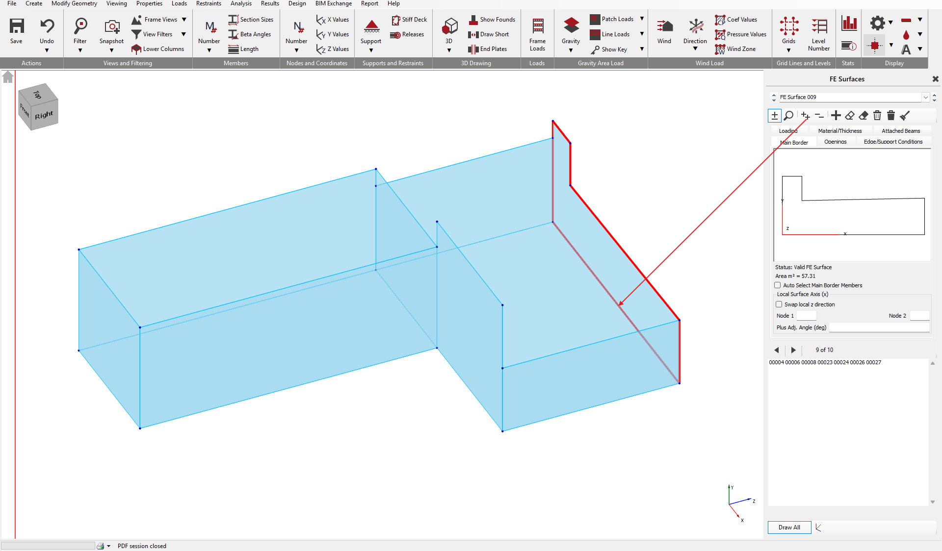
Navigate to the 📄 Create Menu select 📄 Add Members . Draw the wireframe outer perimeter members for your structural layout

Select 📄 Add Slab, Wall, Ramp (FE Surface) .
Click along the perimeter boundaries to form closed loops generating FE Surface regions for both the raft foundation base slab and the vertical bund walls.
Step 2: Assign Material Properties & Section Thickness
📄 Material/Thickness
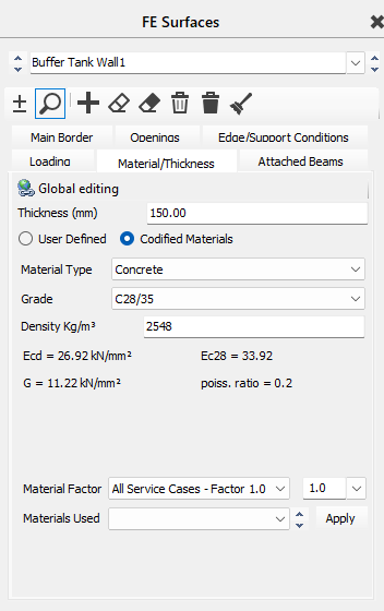
Under FE Surface Properties, define the material properties, grade, and thickness for each surface element:
- Material Type: Set to Concrete.
- Base Raft Slab Thickness:
 (or per design).
 - Bund Wall Thickness:
 (or per design).
 - Concrete Grade: Minimum recommended class for retaining structures.
- Concrete Density:

Step 3: Define Supports & Soil Springs
📄 Edge Restraints and Releases
Soil Spring Stiffness
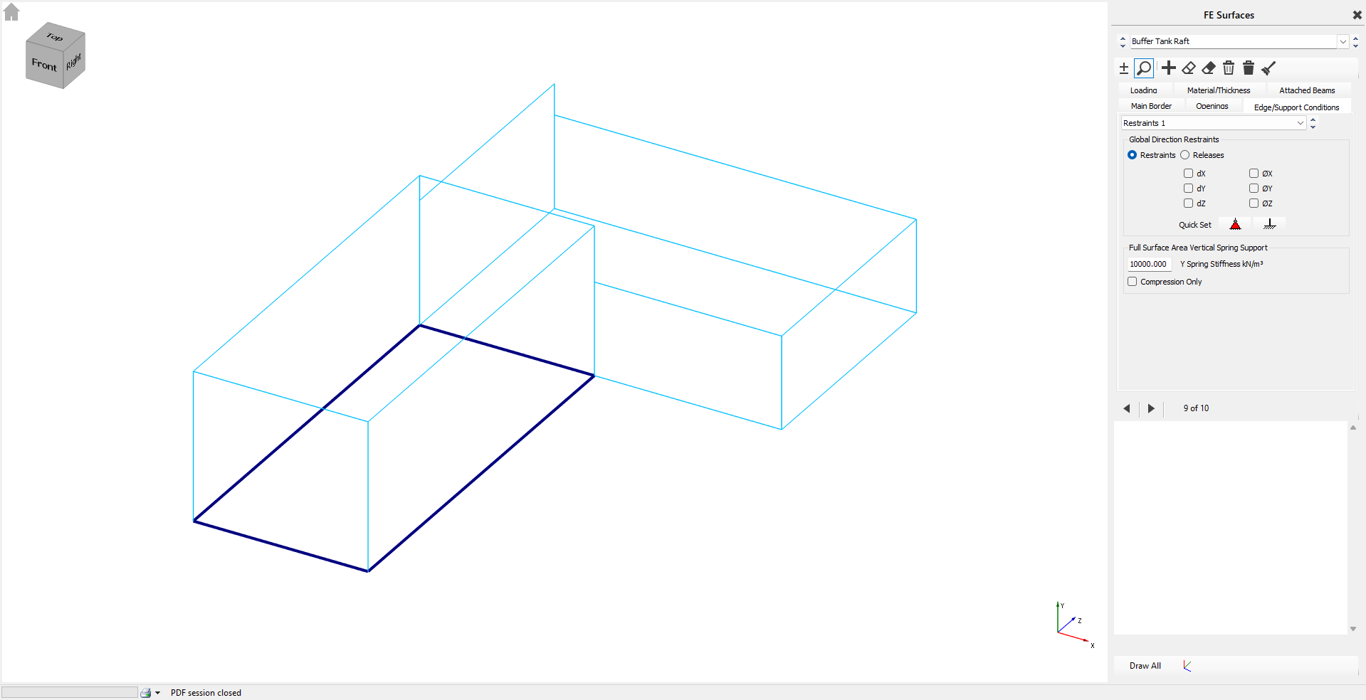
- Select the bottom surface (Raft FE Surface).
- Go to Edge Restraints and Support Options tab.
- Apply a vertical subgrade
reaction spring (
 ) to model ground support
(in this example -
) to model ground support
(in this example -  ).
).
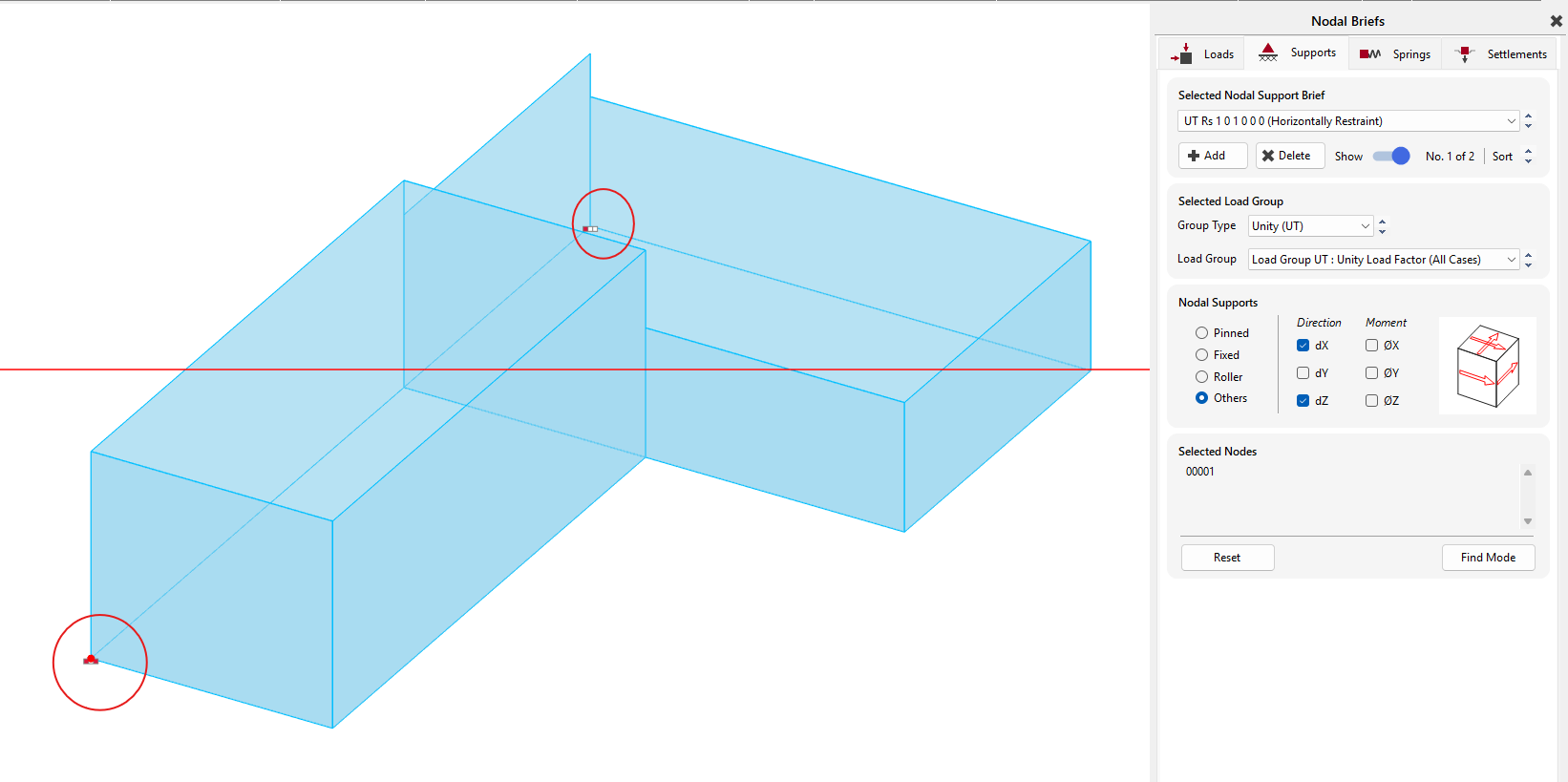
Nodal Restraints for Lateral Stability
- Go to Nodal static supports and assign lateral static restraints to restrain the raft horizontally and prevent rigid body translation during FE matrix solution.
Step 4: Apply Hydrostatic Liquid Pressure & Loads
(Loads application and navigation in FE surfaces-Loading)
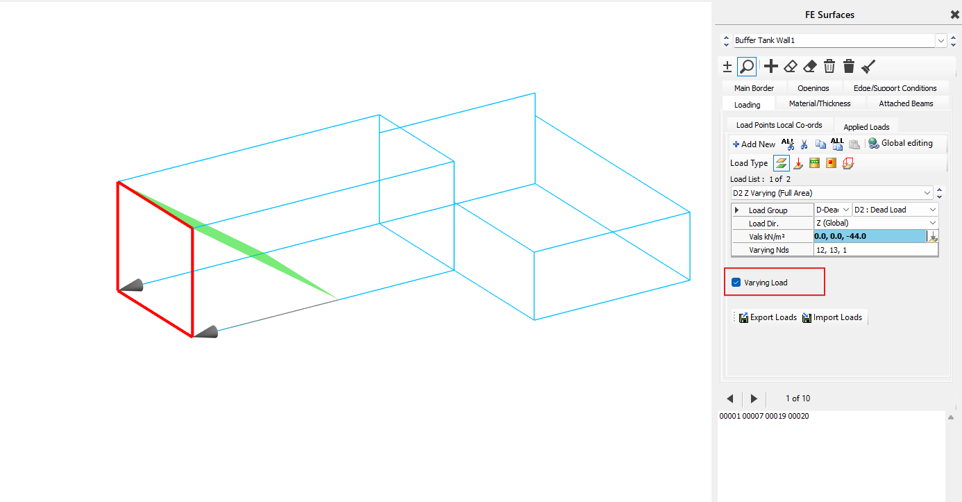
Hydrostatic loading varies linearly from zero at the maximum liquid level to maximum pressure at the wall base.
Navigate to Loading,

Wall Hydrostatic Loads (Full Height)
To apply a full-height triangular load distribution, enable the Varying Load option within the wall surface loading parameters.
- Buffer Tank Walls: Apply a base hydrostatic pressure
of
 .
. - Storage Tank Walls: Apply a base hydrostatic pressure
of
 .
.
Partial Hydrostatic Loads (Submerged Level Below Top of Wall)
If the liquid level does not reach the top of the wall
(e.g.,  freeboard below the top edge). Select
Patch Loads and define the boundary load points to restrict the
pressure zone strictly up to the liquid surface level.
freeboard below the top edge). Select
Patch Loads and define the boundary load points to restrict the
pressure zone strictly up to the liquid surface level.
- Buffer
Tank Walls (Partial): Apply a peak base hydrostatic load of
 .
. - Storage
Tank Walls (Partial): Apply a peak base hydrostatic load of
 .
.

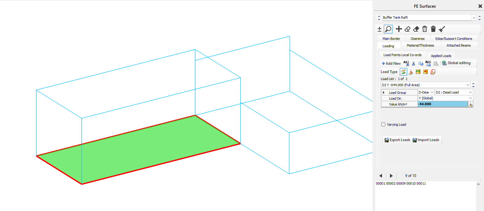
Base Slab Loads
Apply uniform area loads across the raft base slab surfaces to model self-weight, direct liquid head, or equipment/storage loading:
- Buffer
Tank Base Slab: Apply a uniform area load of .
- Water
Storage Tank Base Slab: Apply a uniform area load of .
Step 5: Generate Mesh & Run Static Analysis
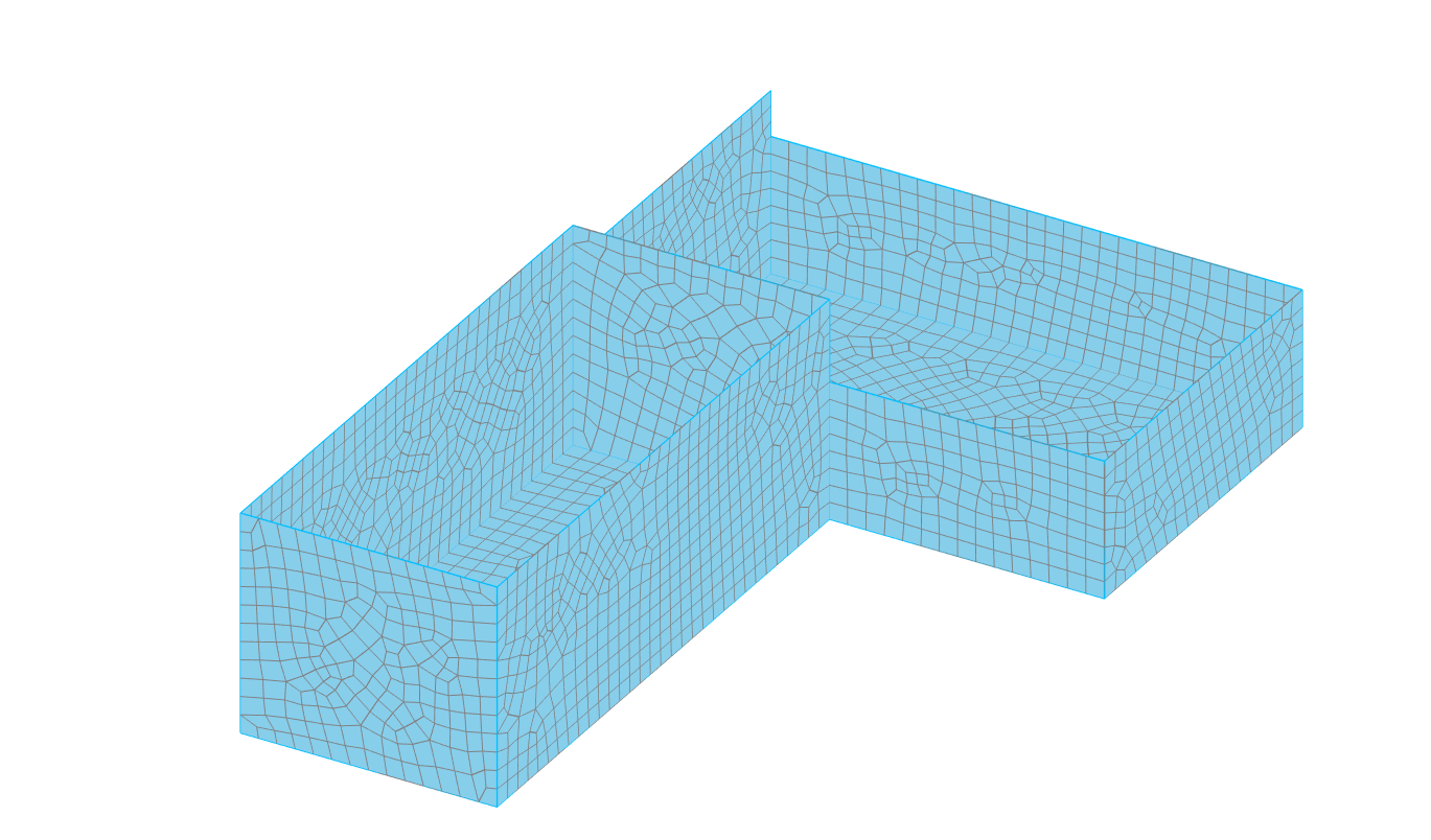
- Go to Analysis Menu > FE Surface Meshing
- In the Finite Element Mesh
Generation Options dialog, set the Default initial mesh size (e.g.,
 or
or  ).
). - In the Finite Element Mesh Generation Options dialog, set the Default initial mesh size (m) (e.g., 0.5 m or 1.0 m).

- Select OK to automatically generate quadrilateral shell element meshes.
- Run the static solver via Analysis > Static Analysis.
Step 6: Review Graphical Results & Deflections
- Open the Graphical Analysis Output window.
- Deflection Check: Select Deflected
Shape to view 3D displacements under each critical SLS load case.

- Surface Forces & Moments:
Switch to Shell Elements and select force, displacement or stress outputs to render contour
maps.
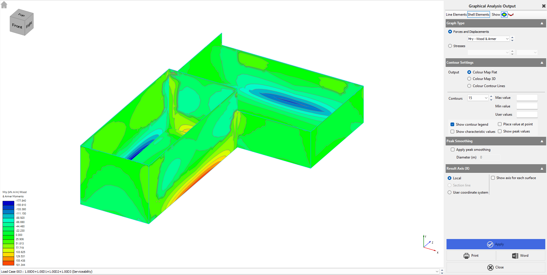
- Support Reactions: Inspect
ground spring reaction contours to ensure no localized tension/uplift occurs
under asymmetrical fluid filling cases.

Step 7: Concrete Slab Design
Go to the Design menu and launch Concrete Slab Design
Define the defaults in the 📄 Default and Auto-Design Settings
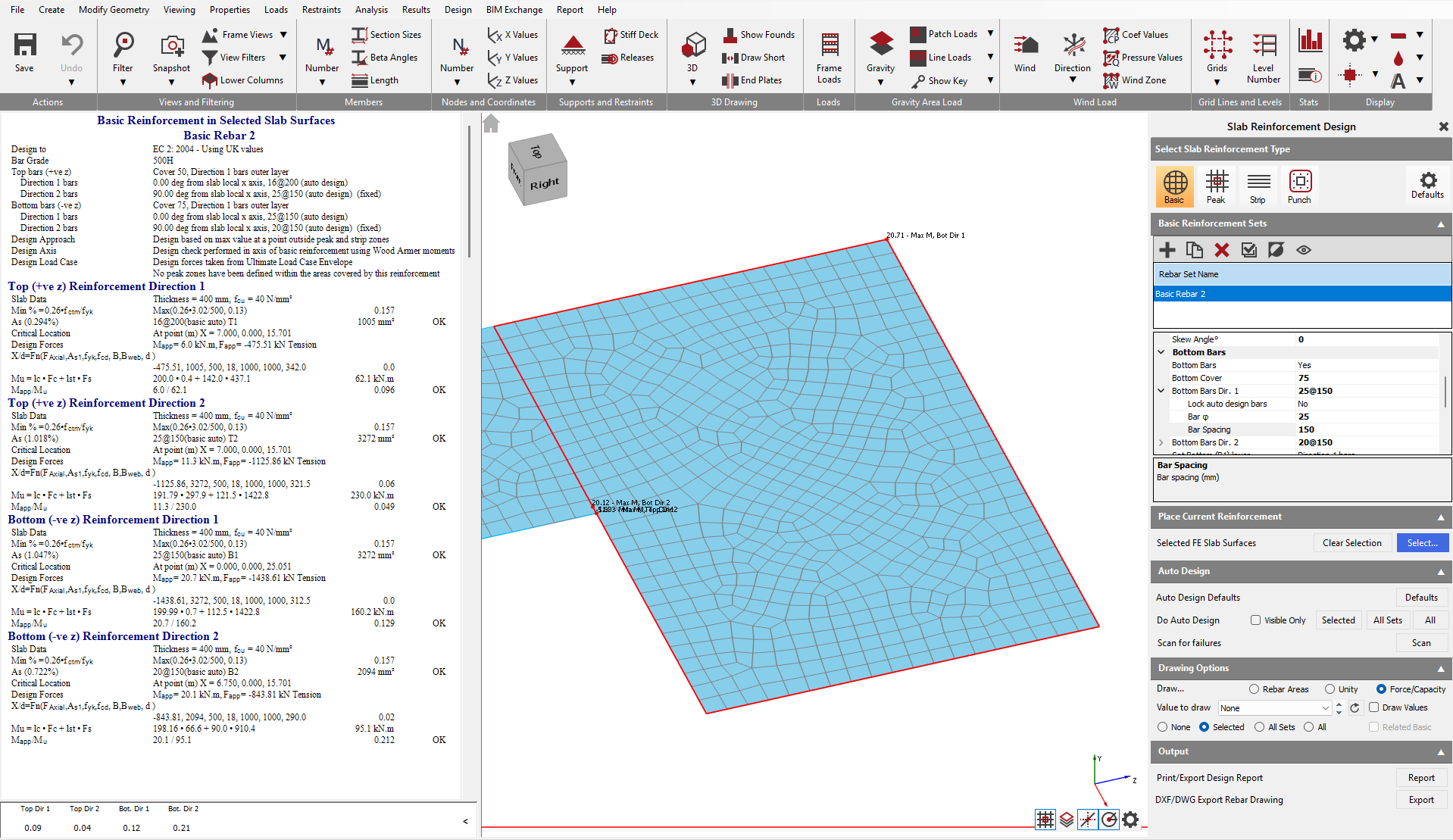
Select a 📄 Basic Regions reinforcement set and select the surface you wish to design (e.g., selecting the Water Storage Tank Raft Slab).
Adjust the proposed top and bottom reinforcement layouts in both orthogonal directions (X and Z axes) and review the capacity .
in this example we have updated the slab depth to 400mm and provided a reinforcemtn of
top X-16@200
top z- 25@150
Bottom x-25@150
bottom z-20@150
Step 8: Concrete Wall Design
Go to the Design menu and launch Concrete wall Design
Define the defaults in the Shear Wall Design Basic Data and Defaults
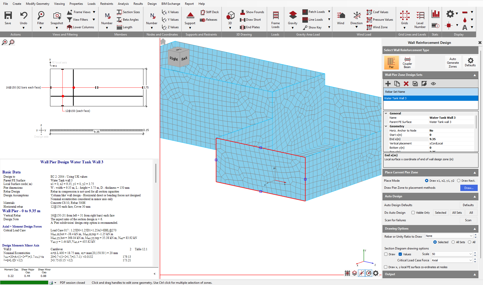
Select a Wall Pier Zone Design Sets and select the surface you wish to design (e.g., selecting the Water Tank wall 3 ).
Place a current pier zone and define the reinforcement and review the design results
Adjust the proposed vertical and horizontal reinforcement layouts on both inside and outside faces, then review the wall design.
The following reinforcement arrangement was assigned to the wall:
- Vertical Rebar (Each Face): 16 dia bars @ 150 mm
- Horizontal Rebar (Each Face): 12 dia bars @ 150 mm