Patch Loads
Patch loads area defined loads which are applied over part of the FE surface area. Patch loads are input using the units kN/m². The area loads are then decomposed by the software into FE nodal loads on the finite elements to which the patch load is applied. Patch loads are defined positionally using Load Points. Hence patch loads can be arbitrary shapes, but their boundary must be a closed simple polygon. That is the boundary of the shape must be closed, planar and with non-intersecting edges.
The Load Direction controls the axis the patch loading is applied in. For gravity loads, this will be the Global y-axis, but since the loads act downwards which the Global y-axis is positive upwards, then the load needs to be input as a negative value. The load is input as a kN/m² value. Patch loads can also be specified to act normal to an FE surface, by selecting the N(Normal) direction. The normal direction is controlled by the local z-axis of the FE surface under consideration. The W (Y Global Full Length) option allows vertical loads to be applied even if the FE surface is itself oriented vertically.
An example of an live loading patch load is shown in the screen below. The Load Points are also displayed.
.png)
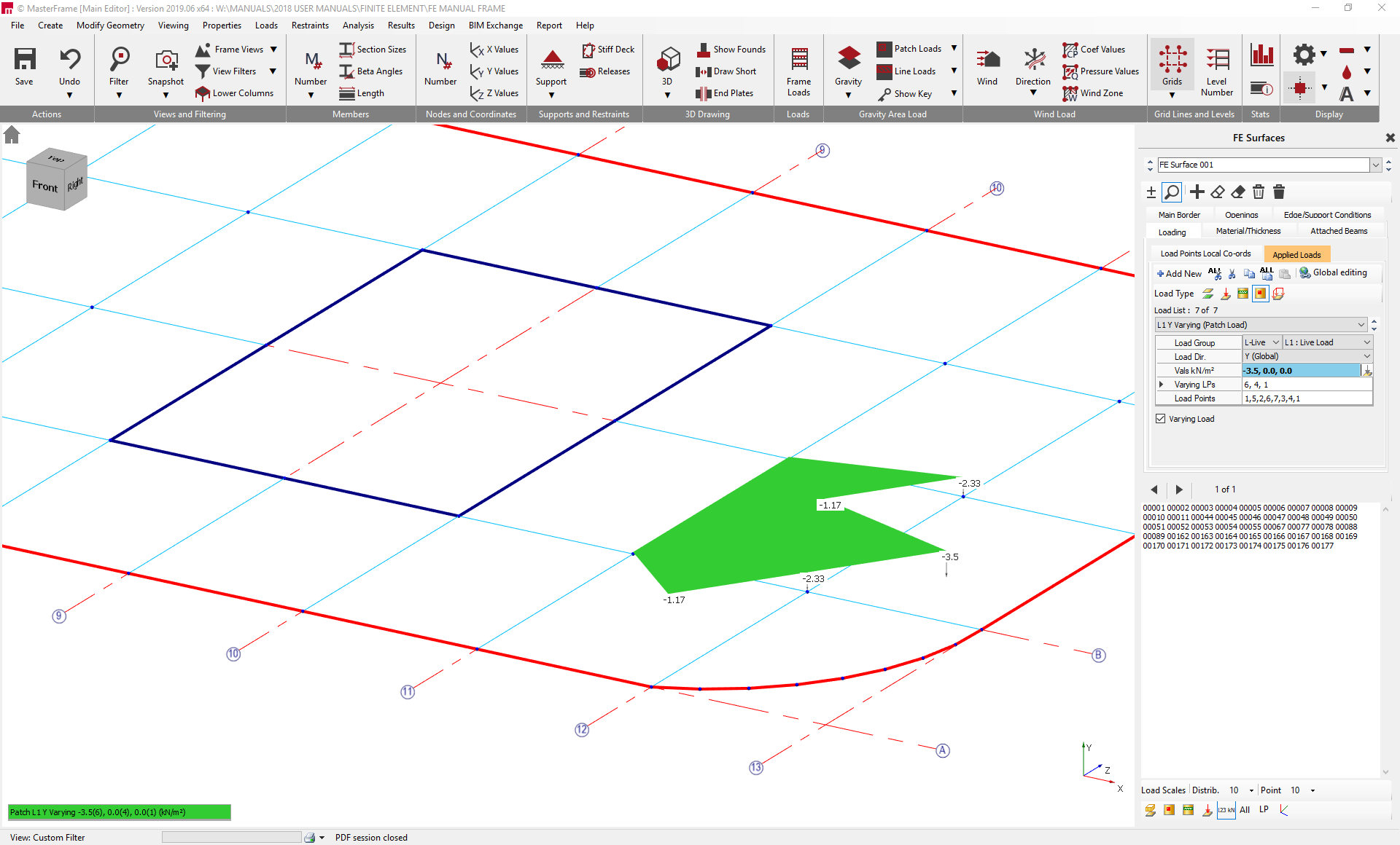
Patch loads can also be set to be variable by checking the Variable Load checkbox. Patch loads are defined by entering three load values and the three load points to which these input values apply. The load values and varying load points are input separated by commas. Variable loads will vary linearly between the input load points. The load intensity at each load point can be viewed graphically on screen by clicking on the .png) icon located at the bottom of the right hand pane.
icon located at the bottom of the right hand pane.
An example of a varying patch load is shown below. The load varies from 0 kN/m² at Load Points 4 and 6, to -3.5kN/m² at load point 1. The load intensity at the other load points is indicated graphically.
While patch loads are associated with a parent FE surface, where they overlap onto other FE surface the loading will still be applied to that surface provided it is in the same plane. Here care must be taken to ensure the local surface normal 'z' direction is consistent across surfaces where the load 'N' normal to surface direction is used. If any part of the patch falls outside of Finite Element Surface, it will not be applied and will be highlighted as a warning during analysis time.