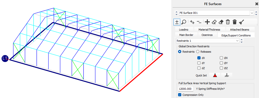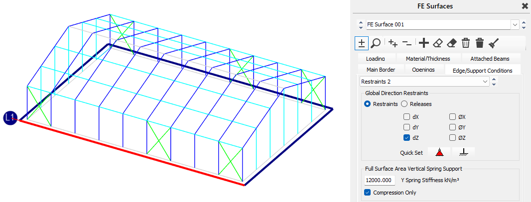
Edge/Support Conditions (Restraints and Releases)
A range of line restraint/support and release conditions can be applied to FE surfaces to reflect the restraints or releases of the structure being modelled. In the case of horizontally FE surfaces, an area based linearly elastic spring stiffness can also be defined, with the spring being set as either compression/tension or compression only.
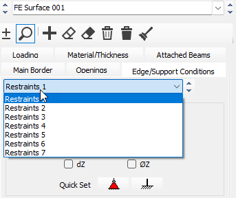
Up to 7 restraint and/or release conditions can be applied to any one FE surface, and the restraint or release condition can be applied to multiple members. Restraint conditions can be applied to any FE surface edge member or internal member of an FE surface. Releases can only be applied to edge members of an FE surface.
Both the restraint and releases are applied by selecting a member along with the restraint or release condition is to be considered. In the case of restraints which can be applied internally to an FE surface, this then requires a line member be included over which to apply the restraint condition.
We can review the different FE Edge Support and Release conditions via the Display Settings -> Finite Element Display Options. These options are:
- Label Continuous Supports
- Label Edge Releases
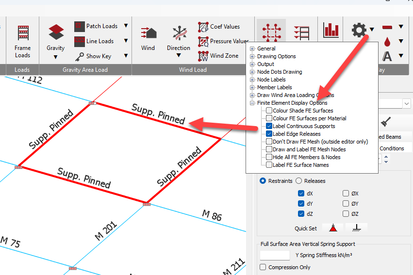
Although the restraints and/or releases are defined over a line, the software converts the line condition to apply to the relevant nodes of the FE mesh. The line element used to define the length over which the restraint or release applies is not in itself significant and unless it is also an attached beam, the line element will be automatically set to dummy FE member and it does not contribute to the FE surface stiffness nor affect the analysis.
Where support conditions are to be applied at specific points, rather than along a line, then the MasterFrame 📄 Nodal Supportsnodal supports should be used to define the support condition for nodes which lie in the plane of the FE surface. The FE mesh will incorporate these nodes into the FE surface and hence incorporate the nodal support condition into the FE surface.
.png)
Restraints
A restraint can be defined to act in each of the six degrees of freedom. These degrees of freedom are:
- dx - translation in the Global x direction
- dy - translation in the Global y direction
- dz - translation in the Global z direction
- θx - rotation about the Global x-axis
- θy - rotation about the Global y-axis
- θz - rotation about the Global z-axis
Translational restraints prevent the movement in the global axis directions, while rotational restraints prevent rotation. Both translational and rotational restraints can be combined to create a variety of restraint conditions.
To add a restraint condition to a line or on an FE surface, the process is as follows:
- Select a Restraint Number from the Restraint drop down.
- Input the restraint condition by check the required translation and/or rotational restraints check boxes.
- Activate the selection mode by clicking on the
.png) icon
icon - Select the members representing the line of restraint by using the mouse pointer and left-clicking. Members can also be selected by windowing around them. Selected members will highlight in red in the graphics window. The selected member numbers will also appear in the right hand pane.
The Restraint area offers two Quick Set set up buttons to quickly pick restraint conditions. The .png) will pick all three translational restraints to give a linear equivalent to a pinned nodal support. The
will pick all three translational restraints to give a linear equivalent to a pinned nodal support. The .png) icon will automatically select all translational and rotational restraints, in a linear equivalent to a fixed nodal support.
icon will automatically select all translational and rotational restraints, in a linear equivalent to a fixed nodal support.
Releases
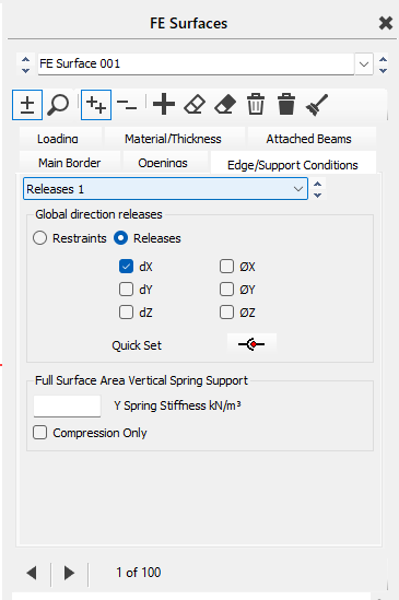
To releases can be defined to act in the following size degrees of freedom, as per the restraints. The degrees of freedom for releases are
- dX- translation in the Global X direction
- dY - translation in the Global X direction
- dZ - translation in the Global X direction
- θX - rotation about the Global X-axis
- θY - rotation about the Global X-axis
- θZ - rotation about the Global X-axis
Releases allow the boundary or part of the boundary to translate or rotate in the specified release axis direction. Thus releases allow for specific translations or rotations between FE surfaces. An example of the use of edge releases would be a joint in a slab where shear transfer is possible but no moment transfer. In this case, one of the FE surfaces would be released in the theta-X, -Y and -Z (Global) axes along their common boundary, thereby allowing the FE surfaces to rotate independently of each other. In this case there would be no need to release both surfaces along the common boundary.
To add release to boundary members, the process is as follows:
- Select a Release Number from the Restraint drop down. Release numbers or conditions are sets of edge release settings ,each case stores a specific combination of degrees of freedom.
- Input the release condition by check the required translation and/or rotational releases check boxes.
- Activate the selection mode by clicking on the icon
- Select the members representing the line of release by using the mouse pointer and left-clicking. Members can also be selected by windowing around them. Selected members will highlight in red in the graphics window. The selected member numbers will also appear in the right hand pane.
Releases are only active at the boundary between FE surfaces. Therefore, at the edge of an FE surface where it does not bound another FE surface, no releases conditions are required. For example, on the outside edge of a slab, where the slab has a free edge, the slab edge will be free to rotate since it is not constrained rotationally by any other FE surface and so rotational releases are not required.
The .png) quick select icon selects the rotational releases.
quick select icon selects the rotational releases.
Vertical Spring Support
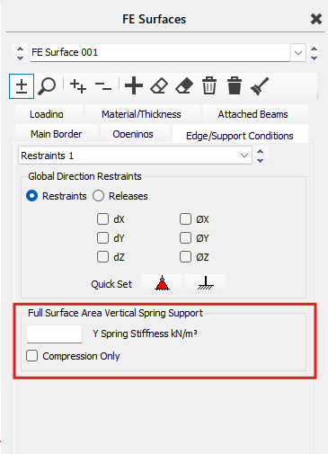
The Full Surface Area Vertical Spring Support option allows for the definition of a vertical spring to be applied over the area of an FE surface. The vertical spring support is only applicable to horizontally orientated FE surfaces. The spring stiffness is defined as kN/m per m².
A vertical spring stiffness is converted into a linear elastic vertical spring on each node of the FE surface. The software automatically uses the mesh size to adjust the individual spring stiffnesses on each node. Each time the mesh is regenerated the software recalculates the spring stiffness at the nodes, so automatically adjusting for the mesh geometry.
The full area vertical spring can be set as compression only by checking the "Compression Only" checkbox. With this option active the spring will not be active in tension. The software will run a non-linear analysis to work out the are where the springs would be in tension, then re-run the analysis ignoring the area of tension. The software will carry out an iterative analysis to determine the area under compression. If the analysis does not converge this will result in an analysis warning. This type of error analysis can occur when a structure has a significant overturning load but inadequate restoring force, meaning that the structure is unstable. This can occur in cases where a structure is being analysed with only wind loading applied, and the self-weight is either inadequate or being ignored in that particular load case.
One common use of the full area vertical spring stiffness is for ground bearing structures. For the determining of an appropriate spring stiffness for use in the design of ground bearing elements, reference should be made to an appropriate resource.
Where a full area Vertical Spring Support is used in conjunction with an FE surface, the FE results are can be used to display the support reaction under the FE surface. For further details, refer to the FE results section of this manual.
Horizontal Restraint to Slabs
The Full Surface Area Vertical Spring Support provides vertical restraint only to the model. Lateral restraint may need to be applied separately. In the case of ground-bearing slabs, no frictional resistance against the soil is considered, so it is necessary to provide horizontal restraint to stabilise the model.
Nodal Restraints
- For a long edge running along the x-direction apply an x- and z-restraint at one end and a single z-restraint at the other end.
- For a long edge running along the z-direction apply an x- and z-restraint at one end and a single x-restraint at the other end.
- When no long edges are running along the x- or z-directions, pick one edge and apply an x- and z-restraint at one end. For the other end, if the edge is running closer to the x-direction use a single z-restraint, and if the line is running closer to the z-direction, use a single x-restraint.
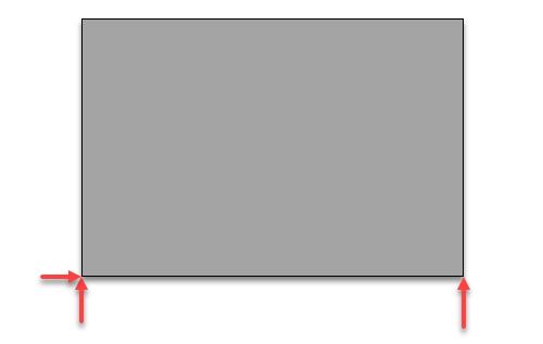
This is often sufficient to stabilise the model, but users should be aware that concentrating the lateral restraint at isolated nodes can lead to large local horizontal reactions and may induce local tension/compression forces in the slab associated with the idealised restraint arrangement.
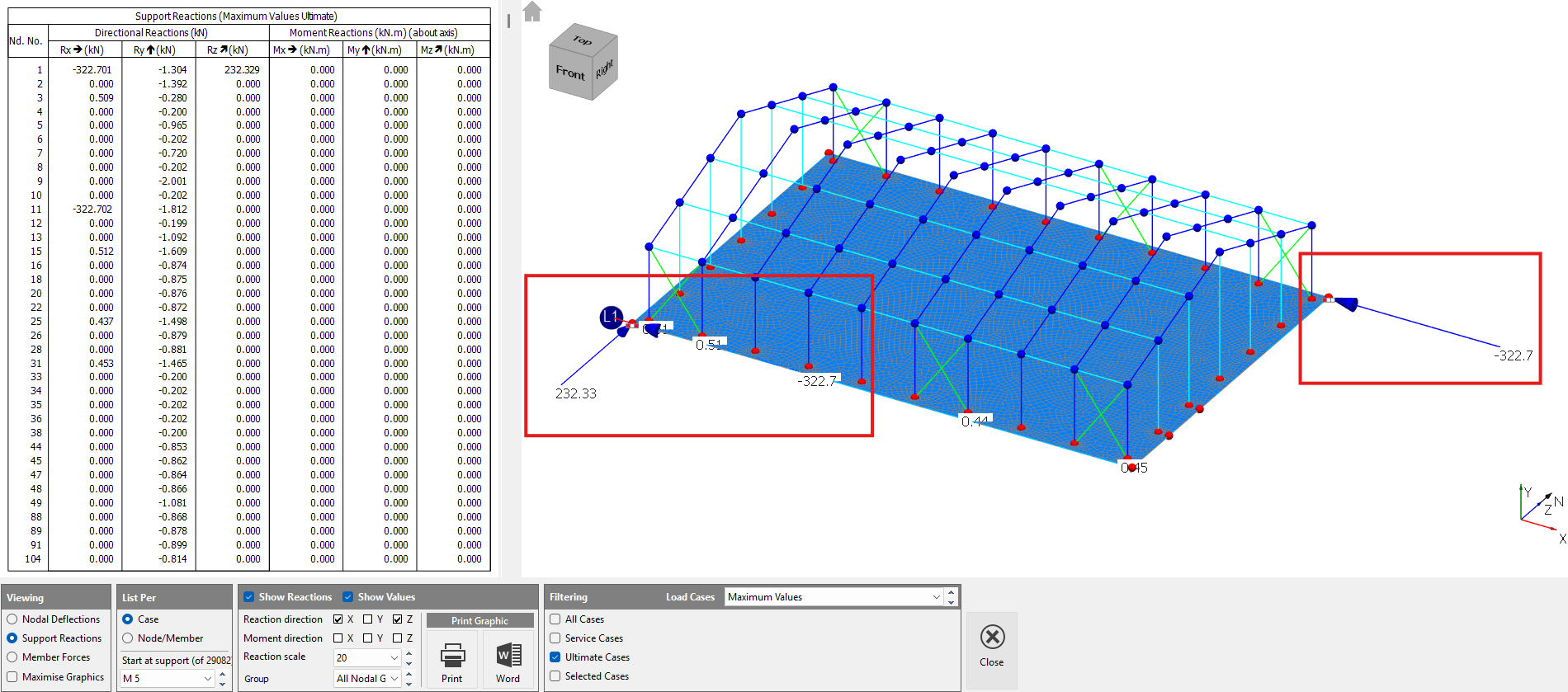

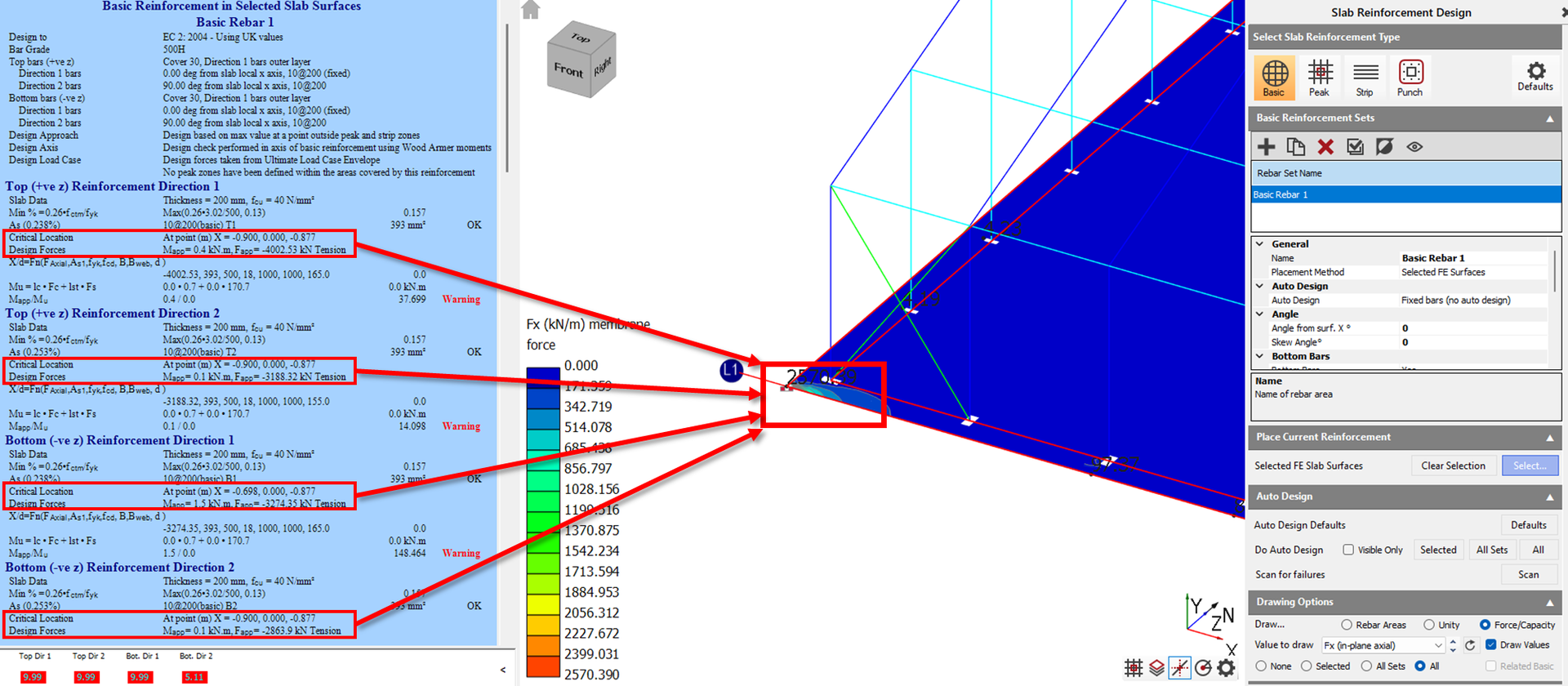
If you have horizontal loads, you need to consider where they going and how they are to be resisted. In ground bearing slabs where the horizontal reaction is provided by mean of distributed surface fiction resistance, we do not have means to model this in the FE surface supports. A series of nodal X and Z spring supports may be a viable modelling approach.
Continuous Edge Restraint
As an alternative, users may apply a continuous edge restraint in a given horizontal direction along one or more slab edges. This can help distribute the horizontal restraint more evenly and avoid localised peak reactions at individual nodal support locations.
However, care is required when using edge restraints, as they may also influence the global force distribution and induce restraint effects that are not representative of the real structure. The user should therefore consider whether the chosen restraint arrangement appropriately reflects the intended physical behaviour of the slab and its interaction with the surrounding structure or ground.