Loading
Loads are applied to an FE surface through the FE Editor under the Loading Tab. The FE surfaces do not interact with the MasterFrame area loads and so loads cannot be applied to an FE surface using the Area Loads.
The FE loads can be applied in a range of load types and also directions. The FE loading also includes Thermal loads, to allow for temperature changes to a structure to be defined. Loads are normally defined using the Global Coordinate system, but it is also possible to specify loads in the direction normal to the FE surface being considered. There are also options to easily specify perimeter loads.
Within the loading area, it is also possible to specify varying loads. Varying loads can be specified for area, line and patch loads. Varying Loads must be linearly varying.
Loads can be applied to an FE surface using📄 Nodal Loading. The nodes will be incorporated into the FE surface and thus will be included in the analysis. However, nodes which are not connected will be removed as part of the model clean up prior to the analysis. Therefore, to use nodal loads, the node must be connected by a member to another masterframe member or node, even if the member is a dummy member. However, for large points loads, where the stress concentration is important, applying nodal loads to the FE surface by using nodal loads has the advantage that the load is applied at a point. This differs for the use of nodal point loads, where the point load need not occur at a nodal position, in which case the nodal load is distributed to the area of the finite element to which it is applied, thus leading to a small distribution of the point stresses.
It is also possible to use the MasterFrame member loads to apply loading to an FE surface where the member will be an attached beam and so will act with the FE surface. In the case where the beam is not to be attached to the FE surface, then the member will act in a similar fashion as a MasterFrame dummy member, with the reactions at the ends of the beams being transferred to the nodes at the ends of the beams. This means the bending in the beam will be ignored by the analysis. Therefore, if the loads are to be applied directly to the FE surface, it is best to not use the member loadings for beams which are not to be attached to the FE surface.
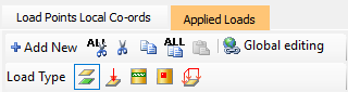
The FE loading can be applied as a full surface area load, patch loads over part of an FE surface, line loads, point loads and perimeter loads. For loads which do not occur over the full surface, the extent of the loads are defined using points on the FE surface. These points are called Load Points (LP). These loads points can be created in a number of ways. Load points can be displayed from within the FE Surfaces area of the software.
It is possible to create loadings which will be applied to other FE surfaces from within another FE surface. For example, if a slab is made up of several FE surfaces, it is possible to define loads for all these surfaces from within one of the FE surfaces. This, for example, it is possible to define a line load in one FE surface which extends beyond the boundary of that surface and onto one or more other surfaces. This feature can simplify the process of creating loads. However. care needs to be taken if surfaces are to be modified or deleted - deleting one surface will delete all loads defined in that FE surface, even if they occur outside that surface.