Attached Beams
Attached beams model the effect of a beam acting compositely with the FE surface. The presence of the beam is used to modify the stiffness of the FE surface, to account for the stiffness and position of the beam relative to the centroid of the FE surface.
.png)
When a beam is attached to an FE surface, it is assumed to act compositely with the FE surface. Thus it is assumed that there will be shear transfer between the beams and the slab.
Within the Attached Beam menu, there are a number of options to quickly define the position of the attached beam relative to the FE surface centreline. The control the position of the beam relative to the FE surface local z axis. It is also possible to input an offset value to manually determine the position of the attached beam.
Within the Attached Beam menu, there are also options to define the width of the concrete flange to be used when considering the beam cross section properties. There is also the option to calculate the bending of the beam element itself for use in the automated design of the steel or concrete designer.
When modelling attached beams, the line element is only modelled as the attached element itself. For an attached steel beam this means the line element should be sized as the steel section itself. In the case of concrete elements, since the FE surface is modelling the slab, the attached element need only be modelled as the additional concrete element. For example, with a downstand beam, the depth of the concrete line element would be set as the overall beam depth minus the slab thickness.
Managing Attached Beams in an FE surface
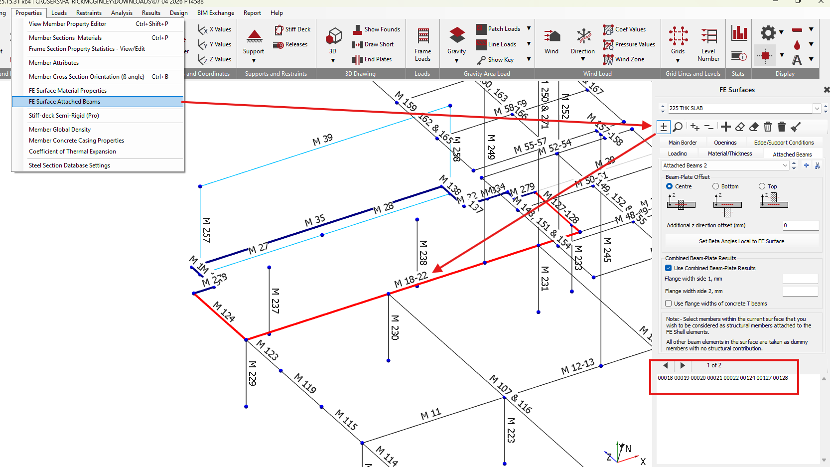
The Attached Beams area can be accessed from the top menu within Masterframe by going to Properties>FE Surface Attached Beams.
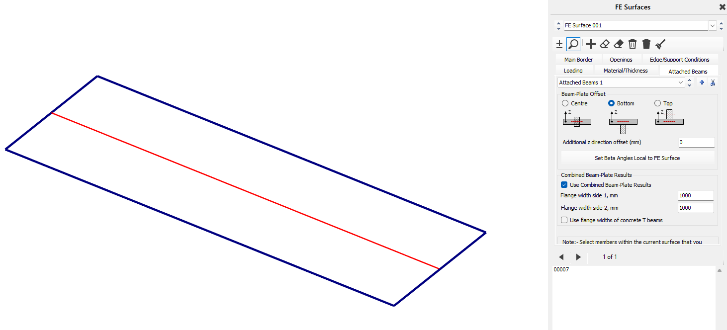
Alternatively, the Attached Beam tab can by going to any of the other FE menu items and then selecting the Attached Beam tab. The layout of the attached beam tab is shown below.
.png)
Add / Remove Attached Beams .png)
To select a line element in the model to make an attached beam, select the icon to enter the select mode, then position the mouse pointer over the line element and select using the left mouse button. The selected element will highlight in red (when viewing the wire frame model) and the member number will appear in the member area in the right hand pane.
Add / Remove Groups .png)

- To add further groupings of attached beams, click on the icon and setup and select the members as required.
- To Remove groups, click on the scissors
 icon
icon
Beam-Plate Offset
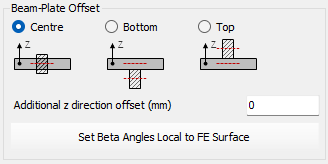
When attaching a beam, there are three options to position the beam relative to the FE surface. These are:
Centre
The centroid of the attached beam will coincide with the centreline of the FE surface. The can also be used when the beam is bottom justified but but non monolithically connected to the slab, hence is providing support to the slab with no shear connection between the beam and slab.
Bottom
The centroid of the attached beam will be positioned such that the top of the beam will be coincident with the bottom of the FE surface.
Top
The centroid of the beam is positioned such that the underside of the attached beam will be coincident with the top surface of the FE surface.
Additional z direction offset
The position of the centroid of the attached beam can be further modified or refined by inputting an Additional z direction offset. This input moves the attached beam offset by the input amount in the local FE surface z-axis.
The beam-plate offset settings apply to all the beams in an attached beam grouping. To set different offsets for beams, additional grouping of attached beams need to be created. This is done by clicking on the icon.
Set Beta Angles Local to FE Surface
For each set of attached beams, the .png) icon amends the line element beta to align the members with the orientation of the FE surface. This is particularly useful for surfaces not aligned with the global axes.
icon amends the line element beta to align the members with the orientation of the FE surface. This is particularly useful for surfaces not aligned with the global axes.
Combined Beam-Plate Results
For each set of attached beams, the Combined Beam-Plate results can be set to control how the line element results for the attached beams are determined. It does not affect the stiffness or the values of forces presented in the FE shell element results.
Consider a down-stand bottom justified concrete beam in a concrete slab. With the 'Combined Beam-Plate results' turned off , the beam line element results will represent only the constituent part of the force in the downstand beam part. Where as for design purposes the engineer may wish to consider the down-stand beam and part of the slab result together in a 'T' like section.
Example: Simply supported beam comprising an FE surface slab as the compression flange and a line element bottom justified attached beam. A UDL area loading of -10kN/m^2 is applies over the slab area. Self weight is ignored.
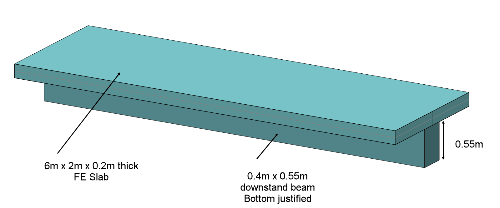
For the combined beam and slab as 'T' section the maximum mid span moment will be 2x-10 x 6^2/8 = 90kN.m
Without using 'Combined results' the results for the beam line element will be as shown.
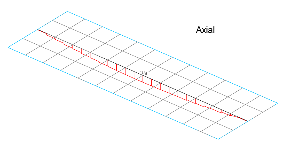
Line element axial force - without combined results
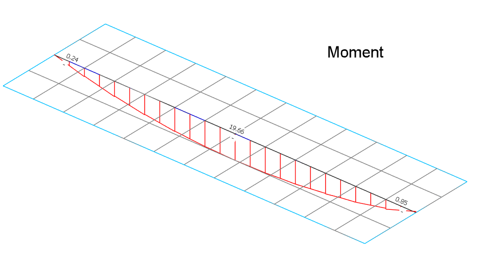
Line element bending moment - without combined results
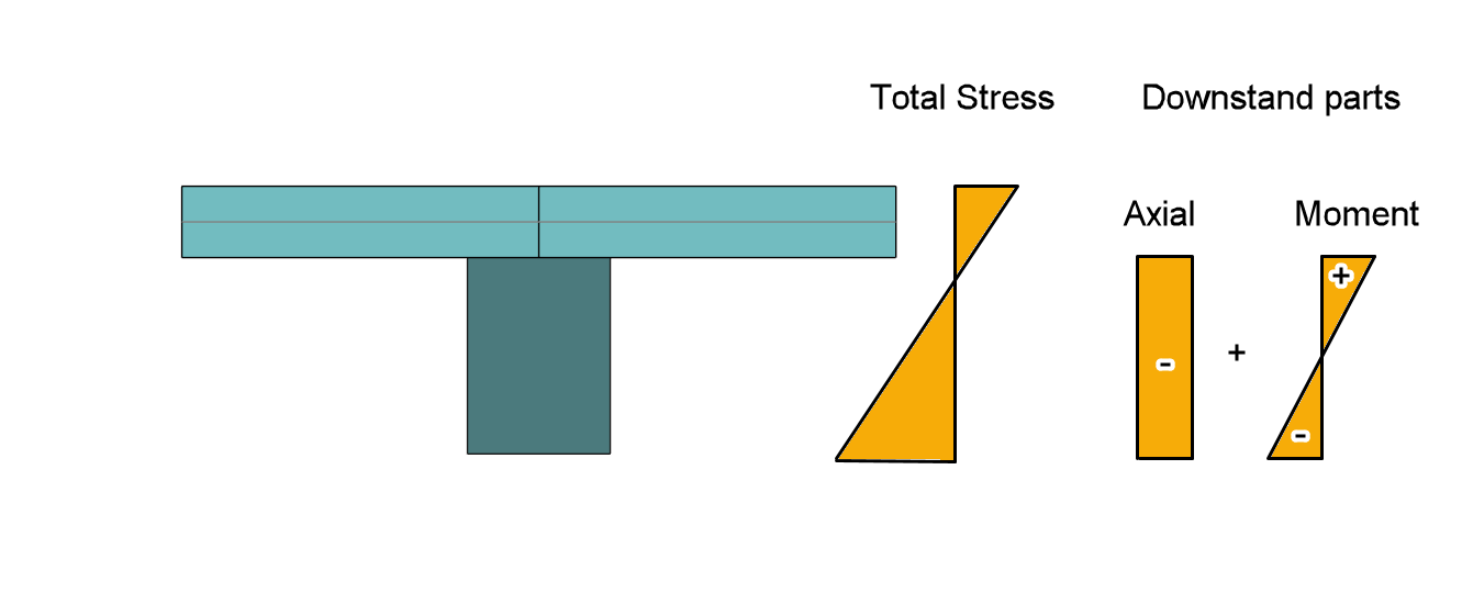
The slab also has its constituent force parts as can be seen in the contour output, showing compression in the slab and a small amount of moment.
With 'Use Combined Beam-Plate results' ON as below, we must indicate what width of the slab results to include in the combined results. In this case we include the full slab compression flange width.
In doing so the beam line element result now shows the expected combined 90 kN.m moment. The line element axial force is also reduced to small value as the net axial force in the complete section is zero.
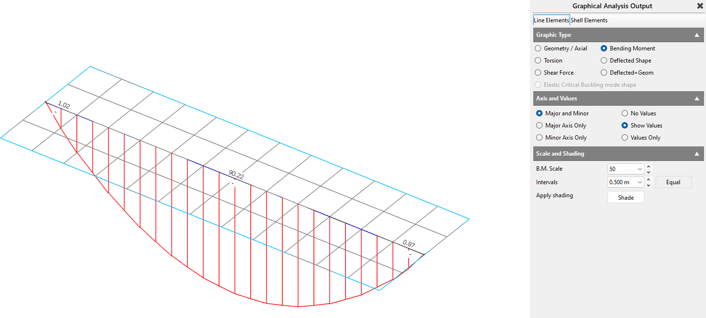
Line element bending moment - with combined results
Associating the combined results on the line element is convenient as it can then be used at design time for the combined concrete 'T' section design.
These options are:
Use Combined Beam-Plate Results ✅
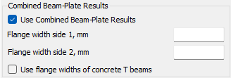
The axial force in the FE surface is used along with the offset of the centroid of the beam element to calculate the bending moment in the beam.
Flange Widths
Flange Side 1 and Flange Side 2 are defined relative to the member direction, that is, from the lower node number to the higher node number.
For a beam shown in plan, if viewed while standing at the lower-numbered node and looking toward the higher-numbered node, Side 1 is the left-hand side and Side 2 is the right-hand side.
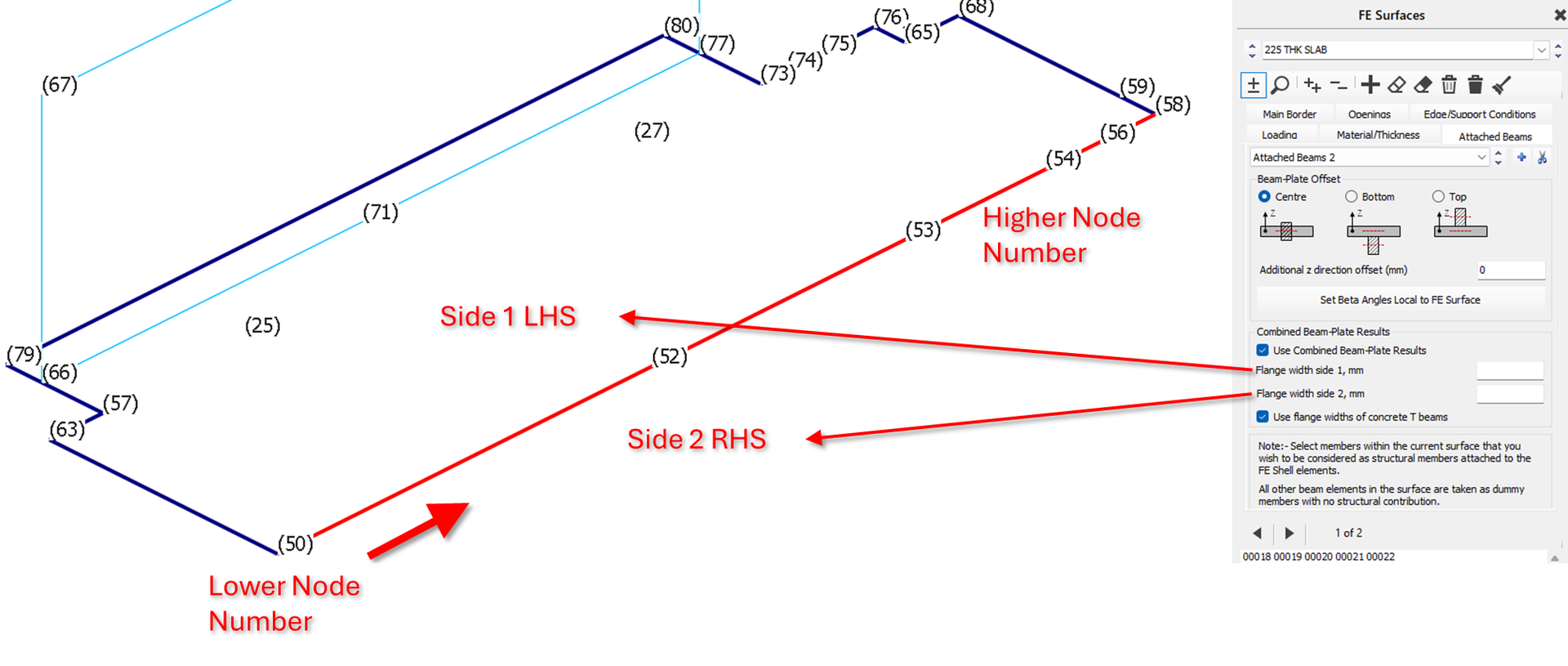
Flange width side 1 (LHS from Node 1->Node 2)
The width of the concrete flange width on side 1 for use in the combination of results when calculating the bending moments in the beam.
Flange width side 2 (RHS from Node 1->Node 2)
The width of the concrete flange width on side 2 for use in the combination of results when calculating the bending moments in the beam
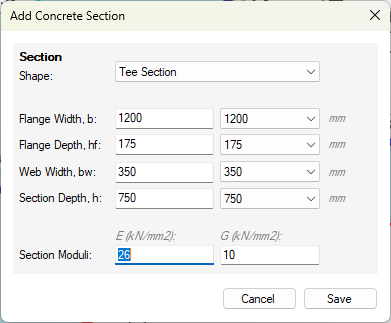
Use Flange widths of Concrete T Beams
Where Concrete T-Beams have been specified, the software will take the flange widths values as defined in the 📄 Member Property Editor.
Attached Beams and FE Surface Edge Releases
FE Surface edge releases, release the connection from an FE Surface edge from another surface edge in accordance with the degrees of freedom released. The Attached beam is associated with a particular FE Surface, and where this is on a common edge with another FE Surface, the attached beam stiffness is theoretically part to the finite shell element of the parent FE surface. Take the example of two FE slab surfaces, 1 and 2, connected on a common edge, where an attached beam is present and associated with FE surfaces 1. Where there is no edge release between the FE surfaces, the attached beam will effectively be full connected to both slab surfaces. Where FE surface 2 has a moment edge release from FE surface 1, this will also apply to the FE attached beam on surface 1. Where FE surface 1 has a moment edge release from FE surface 2, this does not release the FE surface 1 from the attached beam and it remains full connected to the FE shell elements on FE surface 1.
Torsion in Attached Beams and FE Surface Edge Releases
Attached beams are connected to the FE surface in the torsional axis of the attached beam. For example in slab with an edge attached beam, one would expect torsion to develop in the attached beam due to the action of the slab one side of the beam. As described above, in this situation applying a moment direction edge release will not be effective here is releasing the slab from the attached beam in it's torsional axis. What's more apply, torsion member end releases will not be effective, and this apply to the connection of the 1d element end, however the attached beam would remain torsion connected to the FE surface along its length. To achieve this torsional release, an effective approach is to use the 'Ignore Torsion' 📄 Member Attributeson the attached beam. This has the effect of releasing the FE Shell elements from torsional axis of the attached beams, however any other sources of torsion moment in at attached beam will also be released sign the attached beam has no torsion stiffness.