Member Attributes
Often additional attributes need to be applied to various individual members in your frame. Member attributes are applied along with 📄 Member Loading and use the same editing features, such as copy mode and global mode editing.
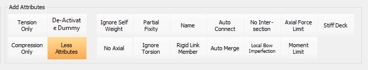
To access these member attributes, select the option from the Properties menu. The various attributes appear at the bottom left of the screen. These can be expanded by clicking on the More Attributes button.
In the same way as member loading, member attributes are associated with a load group, meaning in some attribute types they can be load case dependant. Where an attribute observes the load group and therefore can load case dependant, the load factor for the loading case associated with the load group is NOT applied to the attribute. A load group factor greater than 0.0 activates the attribute for the load cases.
Any attribute assignee to the UT load group will be active in all loading cases.
Member Structural Stiffness Attributes
De-activated Dummy
You can set a member as a De-activated or Dummy member, meaning it is non-structural and produces no stiffness in any degrees of freedom.
These de-activated members are useful in defining the edges of an area loaded panel (📄 Area Loading), wind loaded panel (📄 Wind Panel Loading (Pro)) where no actual member exists but something is required to show an edge for the panel.
No Axial (FREE-AXIAL-LOAD)
The attribute deactivates the axial stiffness component of the member, ensuring that no axial load is transferred through the member. For example, a sliding joint in the direction of the member or a slotted top joint in a portal frame gable column where the rafter is not to be supported by the gable posts. For purely vertical columns that are have multiple analytical member parts, this attribute is automatically only applied to the top most portion, i.e. the top end of the column. In the example given above if the gable column had a secondary beam member at mid height, the columns can accept this axial load as only top end is axially released. Observes load group in loading case.
Partial Fixity
📄 Partial Member End FixityApplies a degree of rotational restraint to one or both ends of a member , defined as a percentage of the member's own bending stiffness. By default, when first applied, the fixity is set to 0% (perfectly pinned) and assigned to the Unity (UT) load group. It must be assigned to a specific load group and is activated in load cases by applying a factor of 1.0 against the relevant load group in the load combination settings.
Ignore-Torsion (No torsion stiff)
Ignore Torsion in the member. The attribute deactivates the torsional stiffness component of the member, ensuring that no torque moment is transferred through the member. This can also be achieved through member end releases in simple line member arrangements, however this feature becomes useful in FE attached beams where there may be undesirable torsion interaction between the attached beam and the FE Surface. Observes load group in loading case. Note that a global frame member ignore torsion option is available in 'Analysis> Global Analysis Options', in which case this attribute is not required.
Stiff Deck
Magnifies x 10000 the bending stiffness of the member in the axis activated with -/+ input, with the three symbols representing the torsion, minor and major axis in that order. For example the default value of 'UT Stiff-Deck -+- (Mt My Mz)' actives the minor axis stiffness magnification. The main application of this feature is when it's applied to all members in a system of floor beams, with the minor axis in the horizonal direction using the '-+-', thus creating a more rigid system of members in this direction and producing a diaphragm action, hence the term 'Stiff deck'. Any load applied in the axis of the member that has the stiff deck applied will not produce in member forces but will effectively be transferred to the analytical member ends.
Local Bow imperfections
The attribute has 3 inputs:
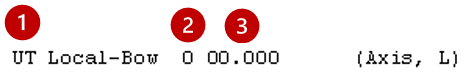
1. Load Group
Single Axis Check
UT for global application. E.g.
UT Local-Bow 0 00.000
Both Axes Checks
If local bow loads are required for both axes, you must apply two separate Local-Bow member attributes to the member, one for each axis therefore the 'UT' load group (global common) should not be used, and each axis local-bow load group should be separated. E.g.
N1 Local-Bow 0 00.000
N2 Local-Bow 1 00.000
2. Axis Selection
The axis for the imperfection loading.
- Enter '0' for the major axis.
- Enter '1' for the minor axis.
3. Length Override (L)
Override the member length used to calculate Ncr and the imperfection value e0.
- If you use the default value of '00.000', the physical length of the member is used for the calculation.
- You can enter a specific value to account for any unmodeled restraints. This will override the calculation of the Ncr figured used in the local-bow 0.25*Ncr limit and e0 equation. If the default 00.000 is used, the physical length of the member is employed in the Ncr and e0 evaluation.
- For example, if a 3.5m member has a mid-point restraint for the minor axis, you could override the length Lz to be 1.75m, which would increase the Ncr value and might resolve the need for the imperfection loading.
- e.g. UT Local-Bow 1 01.750
Member Loading and Behaviour attributes
Ignore Self Weight
Ignore self weight density load on the member. Observes load group in loading case.
The ability to "Ignore Self-Weight" is managed as an attribute for individual members within MasterFrame, typically used to exclude the member's self-generated mass and gravity load from the structural analysis.
Here are the key points regarding this attribute:
Functionality and Location
- Purpose: When this attribute is applied to a member, that specific member's self-weight is disregarded or ignored in the analysis.
- Default Behaviour: By default, the self-weight of structural members is automatically included in the analysis. The self-weight loads are typically checked and modified globally under Loads > Density for Self Weight.
- Interface: You can manage this attribute via the Member Property Editor. Under the Analysis Options section of the editor, there is a setting to indicate whether the member "has self-weight ignored" (Yes/No).
- Loading Context: Although self-weight is handled globally via density settings, it is treated as a property within the analysis options for specific members. If you decide to apply a local 'Density' load type to a member, this method should generally not be used simultaneously with the global density option accessed via the Properties or Loads menus.
- Mass Consideration (Dynamic Analysis): When performing a Dynamic Analysis, MasterFrame automatically calculates the mass from the self-weight of the structure. For this mass contribution to be included, the Member Density for Self Weight ON checkbox must be selected in the Member Self Weight Mass tab.
The Member Attributes interface (accessed through the Properties menu) also explicitly lists the option to "Ignore the Self Weight of a member".
Rigid Link Member
'UT (Rigid Link Member)'. This attribute is automatically assigned to members which create a rigid link between a floor slab and a shear wall. This is usually set up automatically when the shear walls (📄 Add Shear Walls (frame modelling method)) are created from the Create menu. It is a modelling technique used to help transfer the lateral loads from the floor into the shear wall or core, and also assisting the all the shear wall mid columns in a system to act as one entity.
Note the Rigid Link attribute does not change the member stiffness, and it is important that the user assigns member properties of appropriate stiffness for the member acting as a rigid link in the given situation. The purpose this attribute is to mark the member as a fictitious modelling aid member and has the effect of ignoring the member self weight and also excluding the member from 3D drawing and BIM exchange operations. Rigid Link Members are also excluded from the steel design nominal eccentric shear force design moments, i.e if the beam is a rigid link, its end shear force will not be consider to any column it is connected to in the assessment of nominal design moments. Does not observe load group and should remain in UT load group.
Member Non-Linear Stiffness Attributes
Tension Only and Compression Only
Tension Only
Ensures the member has axial stiffness in tension only, with zero axial stiffness in it's compression direction. These are especially useful for simulating behaviour in structures such as bracing systems, cable-supported structures, and tension rods.
Users should be aware of the implications this has for overall model stability. If two elements that are both effectively pin-ended at each end are connected only to each other, no rotational stiffness is provided at the connection. This can result in a global instability (mechanism) within the structural model.
Compression Only
Ensures the member has axial stiffness in compression only, with zero axial stiffness in it's tension direction. This attribute automatically invokes a non-linear analysis. it define structural members that are designed to resist axial forces purely in compression, neglecting their ability to carry tensile forces or bending moments. This attribute is often applied to bracing members, where they act as strut
These attributes are often applied to elements like bracing members.
- A member set as Tension Only will be ignored in the analysis if it incurs a compressive force. Conversely, a member set as Compression Only is treated as a strut.
- If a member has the Tension Only attribute, it will not be automatically intersected with other members
Axial Force Limit (2025)
UT Axial-Limit +000.000 (kN) - Ensures the member cannot receive an axial force value larger than specified in the attribute input value. A negative value sets a tension limit, while positive value sets a compression limit. Observes load group in loading case.
The above three attributes of Tension Only, Compression Only and Axial Limit automatically invokes a non-linear analysis where by the forces are redistributed using a Newton-Raphson iterative approach.
Moment Limit (2025)
UT Mom-Limit 00000.000 (kN.m) - Specifies the plastic moment capacity of the member. For the moment limit to be used it requires the placement of potential plastic hinges and also to activate the second-order plastic analysis option for the load case. 📄 Plastic Analysis Potential plastic hinges can only be places at analytical member ends, therefore the moment limit can only be imposed at these member ends and not at any intermediate point in the member. This moment limit value overrides the automatically generated plastic moment value of class 1 steel 'I' sections. Observes load group in loading case.
Model Auto Connect Member Attributes
The following attributes work in conjunction with the 📄 Model Auto Connect features, which allow automatic connection of modelling member, either on an on-demand basis or on a automatic basis. The following member attributes provide member level control on global model auto-connect behaviour.
Auto Merge
provides member level control for automatically removing redundant nodes in a member.
Auto-Connect
This has an ON/OFF setting. When the setting is ON, the member will always be intersected with other internal intersecting member regardless of the global rules above. With this setting is OFF, the member will not be automatically connected to other internally intersecting members.
No-Intersection
With this attribute present the physical member will always be one analytical member. Even if there are End Intersect conditions, these will not be connected to the member. This behaviour is automatically applied to members set as 'Bracing' member, in which case they do to members they internally intersect with.