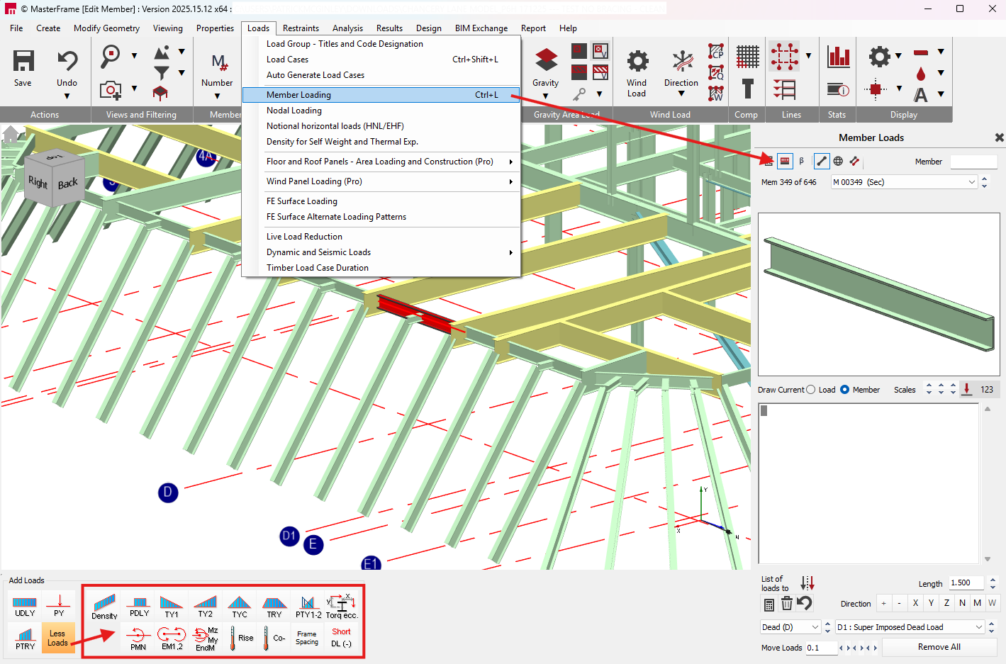
Member Loading
In Member Loading individual members are selected and loads applied to them to act directly on the chosen members. Other methods of applying loads within MasterFrame include 📄 Area Loading and Wind Loading (📄 Wind Panel Loading (Pro)) which apply gravity loads over a floor area or wind loads over a building envelope. These loads are then automatically distributed by the program on to the frame members. See the manual sections on Area Loading and Wind Loading below for details on how to apply these loads to a frame.
To apply member loads, select Member Loading from the Loads menu at the top of the screen. If you are currently in either the 📄 Member Sections and Materials or Member Angle (📄 Member Cross Section Orientation (beta angle)) area you can shortcut to the Member Loading by clicking on the .png) button at the top right of the screen.
button at the top right of the screen.
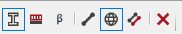
The Member Loading area can be used in three different modes, i.e. Member  , Global
  and Copy To
  modes, in very similar fashion to the section properties and member orientation areas.
In the bottom left of the screen a set of Add Loads icons will appear. To expand these click on the ‘More Loads’ button.
Member Loading Types
.png)
Member Mode
Member Mode is the default mode and perhaps the mode that you will use most frequently.
In Member mode you can apply and edit loads on a member-by-member basis. To do this,
1.Select the member you want to apply or change the loads on. You can select a member by,
a)clicking on it in the main frame geometry area, or
b)if you know the member number you wish to edit then you enter the number in the
 box, or
c)by selecting the member number from the
.png) drop list
drop list
The selected member is highlighted in 3D member profile in the frame geometry window. For this reason it is recommended not to turn on the global 3D member profile option from the top tool bar while working in this area.
Using the Member Loading application buttons apply the desired load types on the member. The loads will appear in the list of loads in the loads editing area.
Use the Loads Editing Area to define the magnitude, direction and load group of each load. See Using the Loads Editing Area below.
While in member mode all changes made in the loads editing area are automatically applied to the selected member. All changes made affect the current selected member only.
When you select a member in member mode, the current member loads on that member are listed in the loads editing area. Therefore member mode can be used to investigate the current loads on members.
Global Mode
Global mode is used to change the member loads on a group of members that have the same pattern of loads or single load applied. In other words global mode can be used to change all occurrences of the same single load/load pattern at once.
Global mode groups member together that have the same single load or load pattern depending on which option is selected. Beneath the global mode icon the drop list indicates how many different member groups have been created, i.e. how many different single load/load patterns are currently applied in the frame.
The difference between the single load and load pattern options is best understood by the following simple example. The four members shown have member loads applied to them.
.png)
While in Global (Load Pattern) mode the program will create a group of the members that have the same configuration of loads applied. Hence here three groups will be generated comprising of,
Member Load Group 001 – M1
Member Load Group 002 – M2 and M3
Member Load Group 003 – M4
No Loads – in this example there are no members in the group since all members are loaded.
When in Global (Single Load) mode the members that have the same single item of load applied will be grouped together. Since in this example only two different items of load exist only two groups have been created.
D1 UDLY –005.00 (kN/m) – M1, M2 & M3
L1 UDLY –007.00 (kN/m) – M2, M3 & M4

To change member loads while in global mode,
- Click on the
 icon to switch to Global mode.
 - Select to work in either single load or load pattern, depending on how you wish to change your loads.
- .Select the existing Single Load/ Load Pattern you wish to change from the drop list.
The members in the group are highlighted in red on the screen, i.e. the highlighted members all have the same single load or pattern of loads.
- Edit the member loads in the loads editing area. Items of load can also be either added or deleted. See Using the Loads Editing Area below.
As in member mode the changes are applied automatically to all members in the currently selected group. Once you are finished in Global mode it is recommended that you return to the Member mode.
Copy To Mode
This is one of the most powerful editing modes, which is used for copying an arrangement of member load(s) to a member or group of members in one operation.
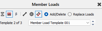
The key concept in Copy To mode is that the List of Loads in the Loads Editing Area becomes the template of information to be pasted onto the members you select. In this sense the Copy To mode differs greatly from the Member and Global modes in that if you change information in the List of Loads, you are not changing any existing loads on the frame. Copy To can be used can be used in either Add/Delete or Replace Loads mode.
In Copy To (Add/Delete) mode the loads in the template (list of loads) are applied to selected members in addition to any existing loads. If the loads that are being copied already exist on a selected member then the loads are deleted from that member.
In Copy To (Replace Loads) mode the loads that are being copied will replace any existing loads on the selected members.
To use the Copy To mode,
- .Click on the
 icon to switch to Copy To mode.
 - Select to work in either Add/Delete or Replace Loads.
- Set up the loads to be copied in the template. This can be done either by,
a)Selecting an existing pattern of loads (Member Load Template) or existing single load from the drop list.
b)Using the Loads Editing Area.
As you edit the loads in the template, members that match the modified template are shown in red. All other members are shown in black
1.Paste this information onto the frame by selecting member(s) in the frame geometry area. You can select member(s) by,
a)Clicking on individual members.
b)Windowing a group of members
In Copy To (Add/Delete) mode, when you select members the loads in the template are applied to the members in black and removed from members in red. Hence the Copy To can be used to add and remove member loads.
Copy To mode can continue to be used by repeating steps 3 and 4.
Using The Loads Editing Area
The list of loads in the editing area represents the loads on the selected member when in Member mode, the loads on a group of members when in Global mode, and the loads to be copied to members when in Copy To mode.
To add loads to the list click on one of the loads type application buttons. Each of these loads types is described in further detail below.
.png)
The loads added will appear on the list on the right of the screen. The load definition in the list will contain information about its Load Group, load type, direction, magnitude, and dimensions (where applicable).
.png)
A typical example of a member point load PY is shown below.
D1 PY -050.000 1.520 (kN, m) where,
D1 Load Group – Dead Load in Load Set 1
P Load Type. Non-editable
Y Load Direction
-050.00 Load Sign and magnitude
1.520 Distance of the point loads from end1 (lower node number) of the member
(kN, m) Indicates the units for the numerical values in the load type. In this case we can
see that the first value is a load in kNs, while the second value is distance in metres.
Non-editable.
The items in the list of loads can be directly edited from the keyboard. Any editable item can be changed by clicking on the relevant text to position the red cursor. Text can be directly entered from the keyboard starting from the location of the red cursor. The position of the red cursor can be changed using the mouse or using the arrow keys on the keyboard. Note that it is not possible to enter an invalid character for load group and load direction.
To edit a load that has been added to the list:
- Firstly, select the load in the list by clicking on any character in the load definition
- The load group can be changed by either,
a)selecting the load group and load set from the drop lists at the bottom right of the screen
.png) , or
, or
b)Over-typing the load group text, e.g. D1, in the load definition. Click on D to place the red cursor and then type one of the load group letters, i.e. D, L, W or N. The red cursor will move to the number, where a number between 0 and 9 can be typed. The items in the drop list below should change to reflect what has been entered.
3.The load direction can be changed by either,
a)Clicking on one of the load direction buttons
.png) at the bottom right of the screen.
at the bottom right of the screen.
b)Typing the load direction directly in the load definition by entering X, Y, W, Z, N or M from the keyboard. The Load direction types are described in more detail below.
4.Change the numerical values of load magnitude or load distances directly in the load definition from the key board. Note that the position of the decimal point in a value can be changed. The .png) buttons can also be used to change the sign of the forces in the load definition.
buttons can also be used to change the sign of the forces in the load definition.
To delete a load
- Select the load in the list by clicking on any character in the load definition
- Press the
.png) at the bottom right of the screen
at the bottom right of the screen
Other options in the loads editing area include:-
For some items in the load list, the order that they appear in the list can influence their effect. The sort spin button will move the selected load’s position in the list.
.png)
By clicking on the horizontal spin button to the right of the text box the loads will move on the member by the increment in metres specified in the text box. Only member loads with distance definitions are influenced by this function.
.png)
The second spin button will change the load group of all the loads in the list in the order of D, L, W and N. For example, if we have two loads in the list with load groups D1 and L2, then these would be changed to L1 and W2.
.png)
The third spin button will increase or decrease the load set number of all the loads in the list. Again taking the example, as above, the load sets could be changes to D2 and L3.
.png)
Graphical Display of Loads in the Editor
The loads in the list are graphically displayed in the Selected Member graphics window at the top right of the screen.
.png)
The graphical display is controlled by the options at the right of the screen.
Draw Current Member will display a load diagram of the total loads on the member, while the Draw Current Load option will only display the load that is currently selected in the list.
.png)
Spin button to graphically move the origin of the load(s) relative to the centre line of the member
.png)
Increase (up button) /decrease (down button) the graphical scale of the distributed member loads
.png)
Increase (up button) /decrease (down button) the graphical scale of the point member loads
.png)
Display numerical value of current member load or total member loads depending on which Draw Current option is selected. The value displayed is always in kN/m units for the distributed load and kN for point loads.
If the loads are not visible it may be their graphical scale needs to be increased.
The frame load diagram can also be displayed which draws all the loads for the current frame view in the frame geometry area. Press the button in the top tool bar.
.png) See section on the 📑 Top Tool Bar for further description of this utility.
See section on the 📑 Top Tool Bar for further description of this utility.
Load Directions
Each member load type can have a number of different load directions. In a load definition the load direction is indicated by the character at the end of the load type. For example, in the load definition,
D1 UDLY -050.000 (kN/m)
UDL is the load type and Y is the load direction. The various different load directions are described below.
Y Load Direction
Global Y axis, where a negative value of load acts downwards. In the case of distributed loads the load is applied over the length of the member projected onto the XZ plane. On a member aligned with the global Y axis no load will be applied.
X Load Direction
Global X axis, where a positive value of load acts from left to right. In the case of distributed loads the load is applied over the length of the member projected onto the YZ plane. On a member aligned with the global X axis no load will be applied.
.png)
Z Load Direction
Global Z axis, where a positive value of load acts from front to back. In the case of distributed loads the load is applied over the length of the member projected onto the XY plane. On a member aligned with the global Z axis no load will be applied.
.png)
W Load Direction
Y direction distributed load calculated for true member length and not just the X-Z plane projection. Useful for applied self-weight UDL in kN/m units. This load direction is only applicable to the UDL load type
.png)
N Load Direction
Load direction normal to the major axis of the member.
.png)
The positive direction of the load depends on the node numbering of the member, and is found by rotating 90 deg anti-clockwise from direction of member from lower to higher node.
.png) Where n1 is the lower node number.
Where n1 is the lower node number.
M Load Direction
Load direction normal to the minor axis of the member.
.png)