Wind Panel Loading (Pro)
The Wind Panel Loading function when applied to a frame, automatically calculates and applies the weighted external pressure coefficients “Cpe” to be used with each wind loaded panel for each wind direction specified.
Wind Zone Generation
The value of Cpe is dependent on the wind surface angle to the horizontal, the angle between the wind direction and the normal to the wind surface and the wind zone depending on the position of the member within the wind surface and the building as a whole, the typical wind zones from BS 6399 Pt2 are:
- A-D and H-K for walls and inclined walls
- A-G and X-Y for flat roofs, and
- A-J and K-S for monopitch and duopitch roofs.
EC design uses similar lettered zones around a building.
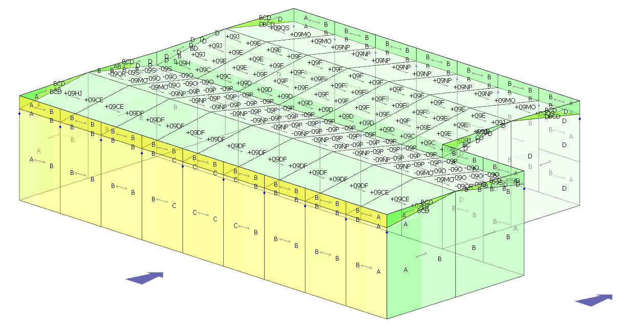
Adjustments are automatically made for corner angles, funnelling effects 0.25b to 1.00b, re-entrant corners and both narrow and wide recesses.
The program will dynamically change all Cpe values for any changes you make to wind directions at any time. All angular values and all member zoning locations are dynamically determined by the program. To ensure maximum flexibility you will however be able to overwrite some or all of these values.
Once a site has been identified in UK or Ireland from the site data maps or wind pressure site data has been manually entered for sites outside the British Isles, the program combines the site dynamic wind pressure with the local Cp values to determine the actual wind pressure on each panel of the building for each of the specified wind directions. These pressures are distributed on to the individual members of the frame as local loads prior to analysis of the frame.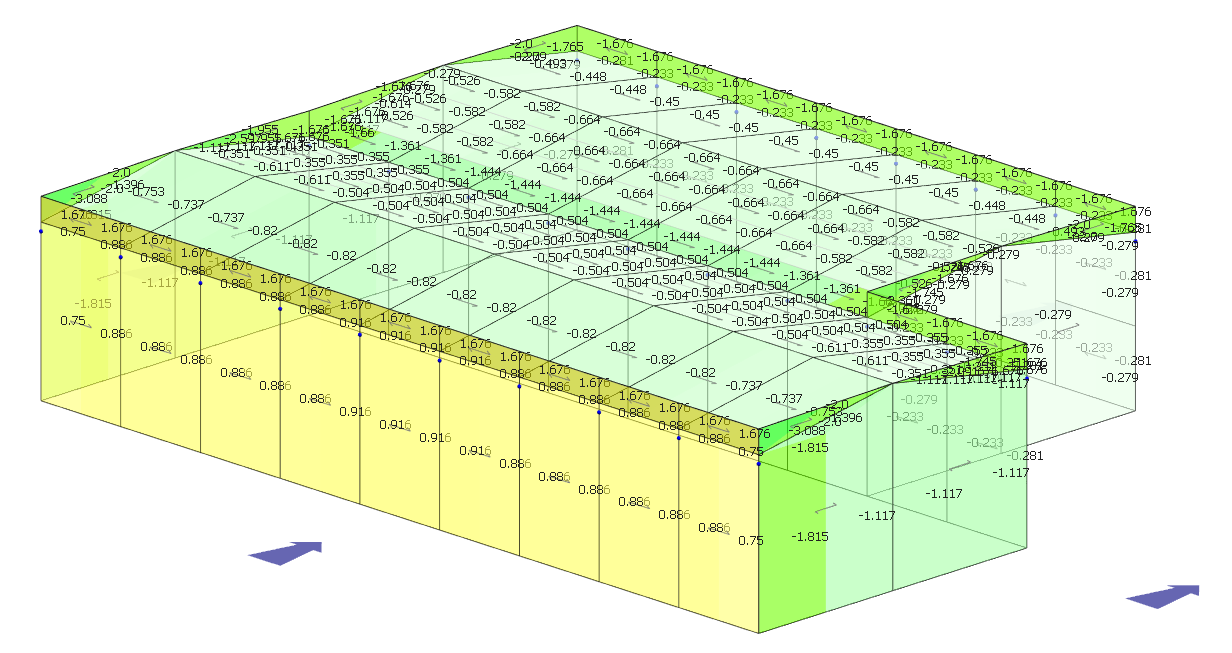
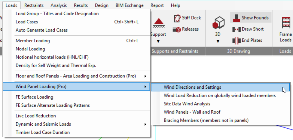
Applying Wind Loading Panels to a Frame

The wind loading is applied to the frame through a series of steps;
- Specify the wind directions and internal pressure and suction coefficients.
- Set up the wind loading cases automatically.
- Select globally wind loaded members on which the wind load reduction will apply.
- Select the wind site from the UK and Ireland map to obtain local data.
- Apply the wind panels to the walls and roofs of the building model.
- Identify ‘bracing’ or non-directly wind loaded members, eg, wall or roof bracing.