Steel Sections
The steel section type provides a comprehensive database of structural steel sections. Select the required steel section type, section size from that type and steel grade from the three drop lists.
There are a number of options which can be applied to the standard steel sections. There individual toolbars are activated by clicking on the respective icon.

Basic Section Properties
The Steel Library can be amended via 📄 Management of 'Standard' User Steel Sections
- Section Type: Specify the type of section required for the member. i.e. UB, UC, RHS etc.
- Grade: Specify the grade of steel used for each member.
- Section Dimensions: This specifies the overall geometry of the chosen section shape.
Here is a shortened, manual-ready version that keeps the important assumptions and distinctions without excess wording:
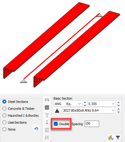
Double Members
The Double Member option duplicates the selected section to create two identical members side by side, represented in the model as a single analytical line element.
When used, MasterSeries assumes:
Both members are the same section and material.
The section properties are all doubled, including the minor axis second moment of area. Therefore no shear connection and no compound action is assumed be the two members
The members are adequately tied together to equally share the load applied
Axial force, bending moments and shear are split equally between the two members.
The total capacity is therefore twice that of the single section.
At analysis stage the member is treated as one element; at design stage the forces are assumed to be shared 50/50 between the two members. Double Members are intended primarily for major-axis bending.
Spacing
A spacing can be specified between the double member for graphical purposes only. It does not affect stiffness, force sharing or design capacity, which always assumes equal load distribution.
Double Members are not suitable where the members differ in size, carry different loads, or are restrained differently. In such cases, the members should be modelled explicitly as separate elements, connected as required.
Back-to-Back / Double Sections
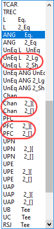
Back-to-back or toe-to-toe arrangements (e.g. double angles or channels) are defined as section types rather than duplicated members.
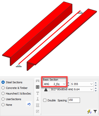
For these sections, the components are treated as a single composite cross-section. Composite action is assumed through suitable interconnection along the member length.
Spacing
Directly affects section properties, particularly minor-axis stiffness and buckling resistance.
Key Distinction
Double Members: two members sharing load equally; spacing does not affect capacity.
Double Sections: one composite section; spacing affects section properties and buckling behaviour.
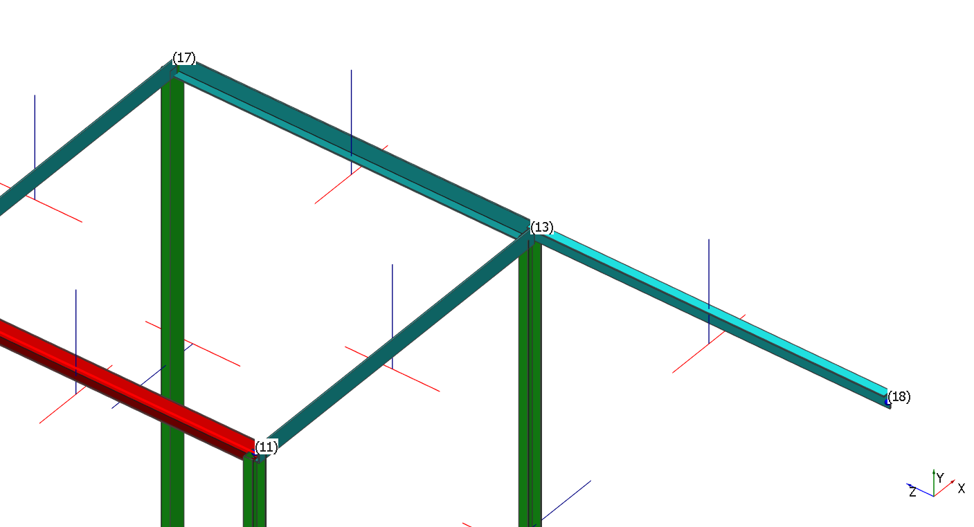
Flats with Asymmetrical Legs – Orientation Definition
For angles with asymmetrical legs, the orientation of each leg is defined relative to the member direction, which runs from the lower node number (Node 1) to the higher node number (Node 2).
This convention is used to consistently define which leg is on each side of the section, ensuring correct interpretation in design calculations and result combinations.
Built-up & ASB
In addition to the above sections, MasterSeries also allows the user to define built up & ASB sections. The asymmetrical sections can be selected from the dropdown list.

If you need to define a custom built-up section, uncheck the “ASB” option at the bottom of the Basic Section. Then manually enter the section properties, including:
- Overall depth (D)
- Top and bottom flange thickness (Ttop & Tbot)
- Web thickness (t)
- Root radius (r)
- Top and bottom flange width (B top & B bot)

Additional Steel Member Properties
In addition to the section type and section size options, within the Section AutoDesign it is possible to amend various properties for a section using the icons. These icons allow:
Haunched and Tapered
- Haunch Specification: The double haunch option allows you to specify haunch lengths (m) and haunch depths from either end of the member. End 1 is always the lower node number of the member. The haunch depths are specified by a H/D ratio, where H is the overall depth of the member (including the haunch) at the node point and D is the depth of the chosen section size.
.png)
- The lengths of the haunches are measured along the local member axis, however by checking the Measure Haunch on Plan
.png) box the haunches will be measured along the horizontal X-Z plane. This will obviously only be of influence in non-horizontal members.
box the haunches will be measured along the horizontal X-Z plane. This will obviously only be of influence in non-horizontal members. - The mm
.png) option allows the overall depth of the haunches to be specified in mm, as opposed to an H/D ratio.
option allows the overall depth of the haunches to be specified in mm, as opposed to an H/D ratio. - The Swap Dim
.png) button simply swaps the haunch length and depth information for the two ends.
button simply swaps the haunch length and depth information for the two ends. - The single haunch option differs from the double haunch in that you enter the uniform length of the member from end 1 and end 2. The haunch depth is specified in the same way as for the double haunch member.
.png)
Section Side Profile
This specifies any specific side profile such as a haunch at each end. See below for further details on how the haunches are specified.


Concrete Encasement
Considers a concrete encasement around steel members only. This allows a modification of the lateral torsional buckling resistance of the member.
When selected, options to define the width b and height h along with the concrete grade become active.
- Uses the BS approach for concrete encased steel column and not that in EC4.
Compound Section

Allows for the addition of a steel member channel to add to the top flange of the beam, or to add an open "I-section" to the web to resist the minor axis moments.
A secondary member can be added to the main section, eg, a channel added to the top flange (for example, a crane beam) or a UB or UC added into the web of the main member (for example, a wind portal column fixed perpendicular to a main column).
.png)
In this case the axial and major axis bending is resisted by the main section while the minor axis moment is resisted by the secondary section.
Additional Plates
Allows the chosen section to be modified to accommodate flange plates (top and/or bottom) and to define the projection of the plate relative to the beam.
Where eccentric loads have been defined, the plate is not designed to handle the defined member loads. Read more within Member Loading: Torq Ecc and Defining Torsional Loads
Cellular section
Creates a cellular section from the original section. In the case of standard I-sections, the cellular beam will be "created" by cutting the original size and welded together. This will result in an increase in the section depth from the original section size. When the original section is specified as a Built-up & ASB, where a plated section is specified, the openings in the web are assumed to be cut without altering the dimensions of the input section size.
The basic dimensions of the cellular section can be specified such as cellular hole spacing, cellular hole diameter and distance from top of slab to top of opening. Holes that are close to critical locations can also be filled in automatically.
.png)
Do is the diameter of the cell as a ratio of the overall beam depth and S is the cell spacing as a ratio of the cell diameter up to a maximum of 1.95 Do. Alternatively, both dimensions can be entered in millimetres.
Discrete web openings
From the Web Openings dialog, you'll have the option to include circular, elongated, rectangular, and notched openings. Sizing and positioning the openings is easy - just specify the height and width (or diameter), along with a top offset and distance from the member's center.

Each Web Opening Set can include a number of different opening types, which will all be drawn and accounted for during analysis.
A Web Opening Set can be applied to a number of member's, and edited from a single interface - there's no need to individually modify web openings for each member.
Discrete web openings can be added to a beam as rectangular, circular and elongated openings or end notches. Within a particular beam there may be several openings which will form an Opening Web Set. This Opening Web Set can then be applied to similar beams to provide the same openings, for example, across a whole grid of beams running in the same direction with service holes on the same lines.
.png)
.png)
Select to Edit Current Member Only or to edit the Opening Web Set at the top of the dialogue box. Editing the set will change these openings on all members to which this set has been applied. If you only want to alter the openings in one member, then use the Current Member Only option.
To set up an opening or series of openings on a beam use the .png) button from the panel below to first add a new item.
button from the panel below to first add a new item.
.png)
In the data entry table above, select the web opening type and fill in the appropriate dimensions for the distance along the beam, etc, etc.
To add another opening to this beam (and set) click again on the button and fill in the appropriate details.
You can use a previous highlighted opening as a template by selecting the Copy item and Add New button .png) and editing the existing data to suit the new opening. Items can be deleted by highlighting them and selecting the
and editing the existing data to suit the new opening. Items can be deleted by highlighting them and selecting the .png) button. The
button. The .png) button will select all the items within a set in one go, or alternatively use the standard Windows Shift and Ctrl buttons to multi-select items.
button will select all the items within a set in one go, or alternatively use the standard Windows Shift and Ctrl buttons to multi-select items.
This process will have created an Opening Web Set which can be applied to other beams where required. Click on the other beams that you want to add this set to. Select the Set that you want to use. Then press the OK button to apply this set of openings to these highlighted beams.
You can add a new Opening Web Set by clicking on the .png) button to the right of the Web Opening Set drop list. This new set can then be populated with opening details. Click on the
button to the right of the Web Opening Set drop list. This new set can then be populated with opening details. Click on the .png) button to delete a set.
button to delete a set.
.png)
Use the Copy and Add New Set button .png) to copy an existing set and add a copy of it as a new set. This new set can be edited as required.
to copy an existing set and add a copy of it as a new set. This new set can be edited as required.
If there are several sets, there may be some duplication of sets or sets that have had all the openings deleted from them. This duplication can be removed using the Delete All Unused Web Opening Sets option .png) .
.
Adding Steel Sections into your database
📄 Management of 'Standard' User Steel Sections
Steel sections can be added and/or imported into the Steel Sections library by the user. This will permanently add the new steel sections to the steel sections library available on the local computer. This database can be shared with other users if required.
- To Add a new steel section to the sections database, see the following technical note - Adding New standard rolled sections into the Sections Database.
- To Import a series of new steel sections to the sections database, see the following technical note - Importing New sections into the Sections Database