Defining Torsional Loads
Date: 04/03/2005
Versions: 2003.04+
Program: MasterFrame
With version 2003.04 of the MasterSeries a new load type was introduced to define torsional loads.

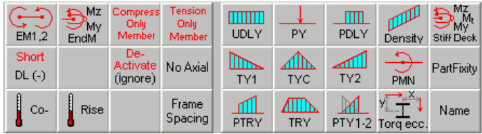
The torq eccentricity option is defined like any other load from the loads button array as shown below. The torq ecc. Is not a load itself but defines the eccentricity from the Shear Centre of other member loads.
The torq eccentricity applies to all subsequent loads, on the current member, until the torque is changed or reset to zero. The torque eccentricity is initially zero at the start of each beam (ie it does NOT carry forward onto the next beam). This means that virtually any physical load can be defined with a torsional offset.
Typical set of loads
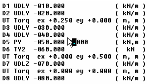
In the above set of loads the load groups are assigned to D1 to D8 for ease of reference.
- D1 to D2 are applied concentrically at Shear Centre
- D3 to D6 are applied with a 250 mm horizontal eccentricity from the Shear Centre
- D7 has a 500 mm vertical eccentricity from the Shear Centre
- D8 is again applied concentrically at Shear Centre
- Always use a UT load factor with a Torq input
- Always insert a Torque with no offsets at the end. This means if you later apply another load then it will not be
- offset by mistake
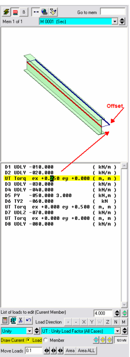
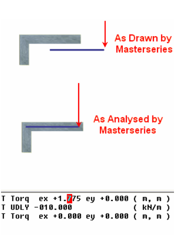
- If you rotate the frame into an isometric view and highlight the Torq load then the load diagram above the loads input area will indicate the direction of offset as shown opposite
Loading on Asymmetrical members
By default all loads are assumed to induce no local torsion on the member. To do this it is assumed that the load is applied through the SHEAR CENTRE. Therefore all torq eccentricity’s are measured from the Shear Centre. The centroid and shear are coincident for Doubly symmetrical sections but not for L’s, [’s, T’s, and built up sections.
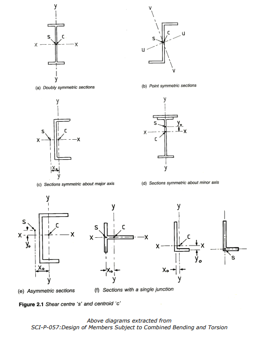
Thus in Single junction members such as L’s and T’s the shear centre is at the intersection of the middle of the flange and web.
Caution: It must be pointed out that the shear centres drawn above are based on the theory for “Thin-Walled” sections and thus are applicable to steel sections. For concrete sections that are reasonably proportioned this will still hold true, but the Engineer will need to use “Engineering Judgment”. Thus to define an eccentric load on an asymmetrical section the you need to know the distance from the shear centre to the centre of your load.
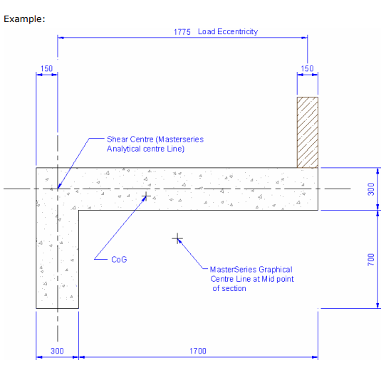
See opposite to define loads as described in the above example
Regards,
MasterSeries Team