Steel and Composite Member Design Groups (Pro)
Design groups can be used to:
- Define a common set of design parameters for a group of members
- Specify that a group of members must be designed to have the same section size
Although not essential, design groups are recommended since they allow a more controllable and rational design to be achieved, particularly when allowing the steel or composite design programs to perform an automatic design.

Information on the inputs can be found in 📄 Steel Design Briefs
Defining a Steel or Composite Group
To define a steel or composite design group:
- Go to Design > Steel and Composite Member Design Groups
- Enter a group name in the drop list, for example, Edge Beams
- From the design group type dropdown list, select the appropriate design brief type
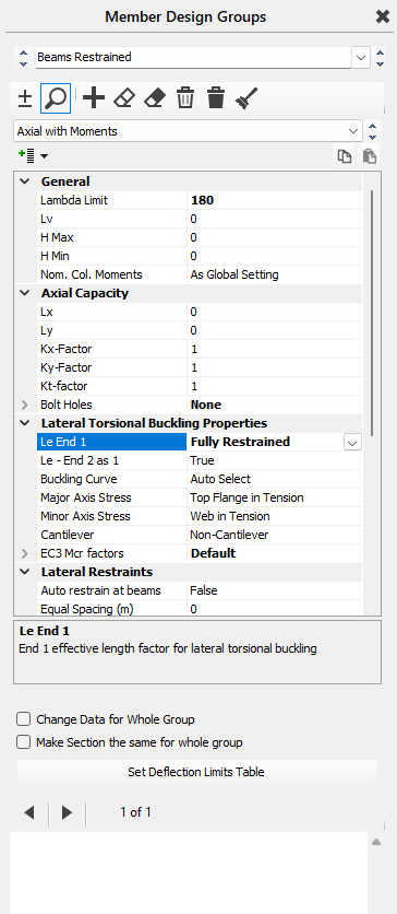
- Enter the common design parameters, i.e. effective lengths, deflection criteria, maximum depth, minimum depth, restraint portion spacing, etc
- Check the “Change data for Whole Group” box to employ the design parameters entered for all members in this group
- Check “Change Section for Whole Group” box if you wish all members in this group to have exactly the same size
- Select the members to be included in this group
Design Briefs
The design brief types include;
- Axial with Moments (📄 Axial Loaded Members with Moments design brief) – ideal for beams and columns with moments, shear and axial loads applied. The effective length ratio can be defined, nominal moments switched on, deflection limits, min and max depth parameters and portion lengths between lateral restraints, etc applied. These will be used in the design of this particular group of members.
- **PRE 2024** Axial with Moments + Appendix G (Annex BB in EC) – as above but also including the Appendix G check for torsional stability of the unrestrained compression flange. From version 2024 onwards, unrestained compression flange checks (Appendix G/Annex BB) are performed along with the 'Axail with Moment' check, therefore this group type is not given.
- 📄 Columns in Simple Construction – useful for columns that have no bending within their length except nominal moments.
- Strut and Tie (📄 Discontinuous Strut and Tie)– useful for diagonal bracing, etc where only axial tension or compression forces are being considered.
- Composite Beam – applied to members which are to be compositely designed. Deflection limits and min and max depth parameters can be set and are particularly useful in automatic design of composite beams.
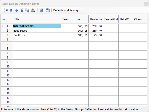
The deflection limits can be check for user defined ""span over" values or defelction limit Set No.s.
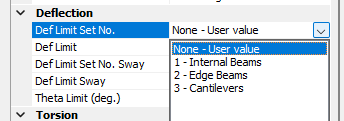
Deflection limit sets can be viewed and edit here using the 'Set Defelction Limits Table' button. They can also be edited in the steel and composite design areas. Deflection limit sets allow different “span over” and absolute mm defelction values to be used for different combinations of serviceability cases. For example, entering “360; 25” in row two under the Live column means that for deflection limit pattern number 2, live load only deflections will be checked against span/360 and also against an absolute deflection of 25.0 mm.