Columns in Simple Construction
The Column in Simple Construction brief is aimed at the design of pinned columns, where the dominant force in the columns is the axial load, and the moments in the column are as a result of the reaction of the beams taken to act 100mm from the web or outer face of the column flange.
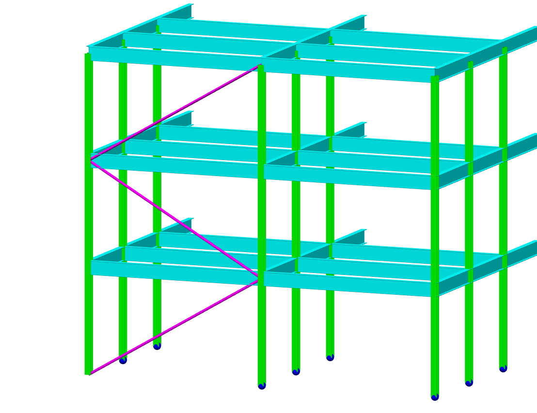
The layout of the Columns in Simple Construction screen is shown below.
.png)
Briefs and Section Sizes
The Briefs and Section Sizes tab contains options to amend the steel member section size, to make the member a compound member (which also provides options to provide plates to the member) and to add web openings. Within the Briefs and Section Sizes, there are also options to carry out an Autodesign on the selected member or on all members visible on screen.
For more detailed information on the AutoDesign area, see the 📄 Automatic Design of Members and 📄 The Automatic Design Menu sections.
Column Simple Design Data
- Kx-factor - effective length coefficient for the major axis compression
- Ky-factor - effective length coefficient for the minor axis compression
- Lambda limit - Slenderness limit. This was originally a BS 5950 check, but was dropped in later versions of the code and does not appear in the Eurocodes. However, it was opted to maintain this input in the steel design.
- FL/UL - the ratio between the factored loads (FL) and unfactored loads (UL). This is used in the British Standard design as part of the check to ensure that Mc = Py*S <= 1.2 py. This check is not used in the EC design so the FL/UL factor is not required.
Beam Nominal Ecc.
The beam nominal load loads eccentricity inputs allow for the shifting of the loads from above the column and the position of the reactions from the incoming beams to be modified in order to modify the nominal moments on the column section.
- Toe plate Tk. (mm) - toe plate thickness. Modifies the position of the beam reaction about the column minor axis to account for a plate between the toes of the column flanges.
- Beam Axis Ecc. Upper /Lower - nominal Eccentricities at top (upper) and bottom (lower) end of the column
- ex1 (mm) - modifies the position of the beam reaction about the major axis. When zero the software defaults to half the column section plus 100mm
- ex2 (mm) - modifies the position of the beam reaction about the major axis. When zero the software defaults to half the column section plus 100mm
- ey1 (mm) - modifies the position of the beam reaction about the minor axis. When zero the software defaults to half the column web (for an I-section) plus 100mm. For closed sections, the software will use half the section width plus 100mm
- ey2 (mm) - modifies the position of the beam reaction about the minor axis. When zero the software defaults to half the column web (for an I-section) plus 100mm. For closed sections, the software will use half the section width plus 100mm
Beam Off Centre Ecc.
The off-centre eccentricity inputs allow for the shifting of the beam eccentricity out of the line of the column section axes. This allows for the modelling of beams connecting off the centre line of the column. The diagrams at the top of the calculation pane update automatically to assist in inputting the desired values.
- Off Centre Ecc. Upper /Lower - Off centre Eccentricities at top (upper) and bottom (lower) end of the column
- cy1 (mm) - off centre eccentricity for beam reaction Fx1. A value of zero means the beam is aligned to the centreline of the column section.
- cy2 (mm) - off centre eccentricity for beam reaction Fx2. A value of zero means the beam is aligned to the centreline of the column section.
- cx1 (mm) - off centre eccentricity for beam reaction Fy1, at the top of the column. A value of zero means the beam is aligned to the centreline of the column section.
- cx2 (mm) - off centre eccentricity for beam reaction Fy2. A value of zero means the beam is aligned to the centreline of the column section.