Discontinuous Strut and Tie
The Discontinuous Strut and Tie brief is aimed at the design of members which have axial loads (either tension or compression) but no bending moments. This brief is intended for use on members forming part of a bracing system for a structure, or for the internal members of pinned trusses. The Discontinuous Strut and Tie will carry out axial load and axial buckling checks, as well as slenderness checks based on the member cross sectional properties.
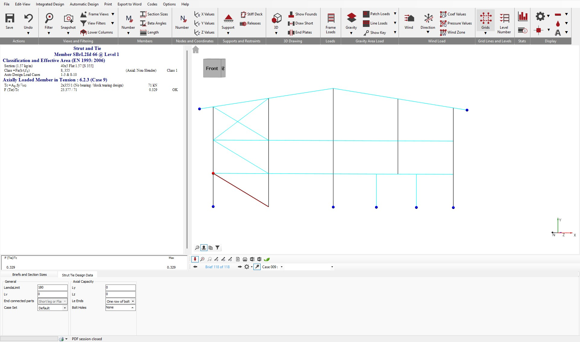
The layout of the Discontinuous Strut and Tie screen is shown below.
Briefs and Section Sizes
The Briefs and Section Sizes tab contains options to amend the steel member section size, to make the member a compound member (which also provides options to provide plates to the member) and to add web openings. Within the Briefs and Section Sizes , there are also options to carry out an Autodesign on the selected member or on all members visible on screen.
For more detailed information on the AutoDesign area, see the 📄 Design of Beams section.
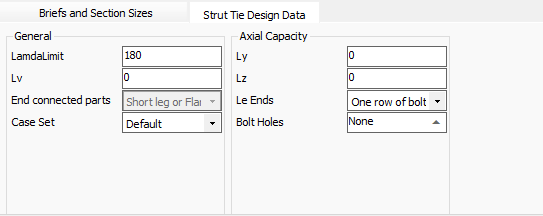
Strut Tie Design Data
The layout of the Strut and Tie area is shown below.
Lambda limit - Slenderness limit. This was originally a BS 5950 check, but was dropped in later versions of the code and does not appear in the Eurocodes. However, it was opted to maintain this input in the steel design.
Lv - the distance between connection locations in a double member. The input is specified in metres (m). If a value of zero is used, the software will default to using the actual member length.
End connected part -Control which parts of the angle or channel member are connected at the ends - affects strut buckling
Lx(Ly) - the length between restraints to the major axis of the member, for use in the axial load buckling design check. A value of zero means the software will use the full member length. For designing a portion of a member, a value greater than the member length can be input.
Ly(Lz) - the length between restraints to the minor axis of the member, for use in the axial load buckling design check. A value of zero means the software will use the full member length. For designing a portion of a member, a value greater than the member length can be input.
Le Ends- Lets user to determine one row of bolt or two rows of bolt has to be considered.
Bolt Holes -For reduction from gross area to tension area
- No. Of Flange Holes - inputs the number of holes to be considered in the member the flange of the member.
- Flange Hole Diameter (mm) - input controls the diameter of the holes to be considered in the flange of the member.
- No. Of Web holes - inputs the number of holes to be considered in the member web.
- Wed hole Diameter (mm) - input controls the diameter of the holes in the member web.
- No. of bolt rows - input controls the number of holes in a single row. For use with angles connected by a single leg.
- Bolt Pitch P1 (mm)- controls the pitch of the bolts in a single row. For use with angles connected by a single leg.
- Bolt edge dist (mm) - controls the edge distance of bolts. For use with angles connected by a single leg.
The drop down at the right hand side of the Strut and Tie area give controls for the number of rows of bolts, the formulae to use in the calculation and, for angles, whether they are connected by the long or short leg.