Final Wind Panel Pressures
The final wind pressure applied to a wind panel is based on a number of factors which can vary between load cases.
- Wind Direction - 1 to 8
- If the load case is classified as 'Local Wind' or 'Overall Wind'
- If the load case Wind combination factor is W, P, or S.
Note Cpi (Int Pres. Co.) & Csi (Int Suc. Co.) are user defined inputs in the wind directions area. - W - external wind alone with no internal pressure Cpe (can be 'Local Wind' or 'Overall Wind')
- P - external wind with internal pressure Cpe+Cpi (always 'Local Wind')
- S - external wind with internal suction Cpe + Csi (always 'Local Wind')
- In BS6399, the wind diagonal. Wind diagonal sets are a member group that are user defined with a wind diagonal value set for the group. This is the size effect factor. A different wind pressure value is created for each wind diagonal value. The wind diagonal set can then be set for the load case. The default wind diagonal of 5m (no reduction) is always included and is classified as the 'Local Wind' case. All other diagonals are classified as 'Overall Wind' cases. Set from 'Loads> Wind Panel Loading> Wind load reduction on globally loaded members'.
- In Euro code the 'Local Wind, vs 'Overall Wind' case setting. In this design code a simple member group is set up to assign members that should be design for over all wind effects, e.g. bracing members in a simple construction steel building. Again the load case be set for 'Local Wind' or 'Overall Wind'. This is a somewhat more simplified equivalent to the BS 6399 diagonal value settings. Set from 'Loads> Wind Panel Loading> Wind load reduction on globally loaded members'.
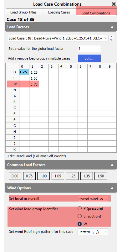
In BS the 'Set local or overall' becomes drop a list of defined wind diagonal member sets. If no members are assigned to the BS wind diagonal or EC overall wind loaded member group, then this drop list will only have one item for local only wind. - 'Lack of Correlation factor' as per En 1991-1-4 7.2.2 (3). This can be as low as 0.85 for certain H/B ratios. In BS6399 this always 0.85. This is applied to the horizontal components of wind force (as per UK NA.2.19), but only when considering overall wind effects.
- In Eurocode the Cs.Cd factor. This represents the product of the Cs (size reduction factor) and Cd (dynamic effect factor). This can be input by the user or calculated in accordance with the UK NA. The Cs.Cd factor is only applied to 'Overall Wind' load cases.
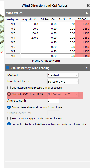
- In BS 6399 a single Dynamic augmentation factor 'Cr' is entered, and is only taken on 'Overall Wind ' cases.
- P1 to P8 and S1 to S8 are always 'Local wind' effect cases.
| Load Case | Wind Type | Internal Pressure Included | Local / Overall | Typical Use |
| W1–W8 | External wind only | ❌ No | Local or Overall | Global building wind effects |
| P1–P8 | External + internal pressure | ✔ Cpe + Cpi | Local only | Worst internal pressure case |
| S1–S8 | External + internal suction | ✔ Cpe + Csi | Local only | Worst internal suction case |
The wind pressure may vary over the height of building is accordance with the code, however for Eurocode this only applies to the windward vertical face.
Hence final wind pressure
- W1 local wind - Panel pressure = Cpe*qp(z)
- W1 overall wind EC - Panel pressure = Cpe*qp(z)*'Lack of correlation'*Cs.Cd
- W1 overall wind BS for a wind diagonal value - Panel pressure = Cpe*qp(a,z)*'Lack of correlation'*(1+Cr), where qp(a,z) is the dynamic wind site pressure at wind diagonal 'a'.
- P1 - Panel pressure = (Cpe+Cpi)*qp(z) - no wind diagonal reduction in BS
- S1- Panel pressure = (Cpe +Csi)*qp(z) - no wind diagonal reduction in BS
- Cpi (Int Pres. Co.) & Csi (Int Suc. Co.) are user defined inputs in the wind directions area. Internal pressures Cpi and Ci pressure are not applied to panels with 'Wind on both sides' set.
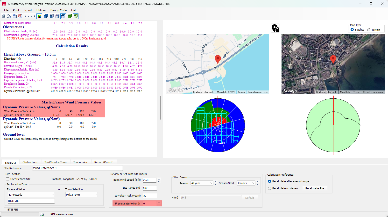
- qp(z) is the peak dynamic wind pressure value for the wind site. This can vary between wind directions and is given in the Wind Analysis output.
Note also the 'Frame angle to to north' will affect these directional wind site pressure values. qp(z) can also vary over the height of a building in accordance with En1991-1-4 Figure 7.4, but only on the windward vertical face (+ve Cpe). Refer to 📄 Wind Panel Pressure on Tall Buildings.
Eurocode (EN 1991-1-4)
| Case Type | Final Panel Pressure |
| W – Local wind | Cpe × qp(z) |
| W – Overall wind | Cpe × qp(z) × Lack-of-correlation × Cs·Cd |
| P | (Cpe + Cpi) × qp(z) |
| S | (Cpe + Csi) × qp(z) |
BS 6399-2
| Case Type | Final Panel Pressure |
| W – Local wind | Cpe × qp(z) |
| W – Overall wind (wind diagonal a) | Cpe × qp(a,z) × 0.85 × (1 + Cr) |
| P | (Cpe + Cpi) × qp(z) |
| S | (Cpe + Csi) × qp(z) |
Notes
qp(a,z) is the site wind pressure evaluated at the wind diagonal length a.
The default diagonal a = 5 m represents local wind (no reduction).
What Is Displayed as “Q” on the Model
| Load Case | Displayed Value |
| W1–W8 (EC) | Cpe × qp′ × Cs·Cd |
| W1–W8 (BS) | Cpe × qp′ × (1 + Cr) |
| P1–P8 | (Cpe + Cpi) × qp |
| S1–S8 | (Cpe + Csi) × qp |
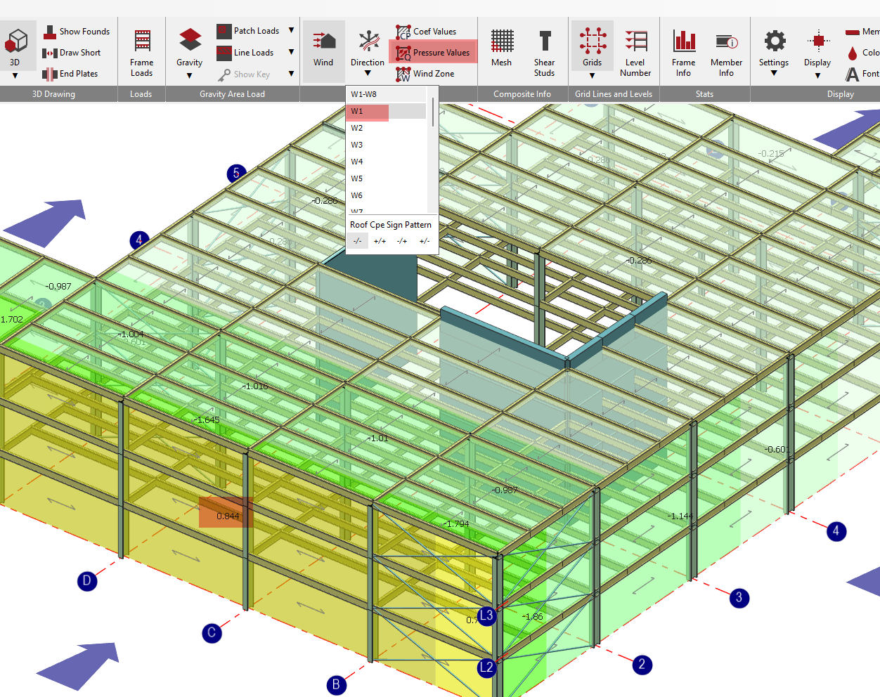
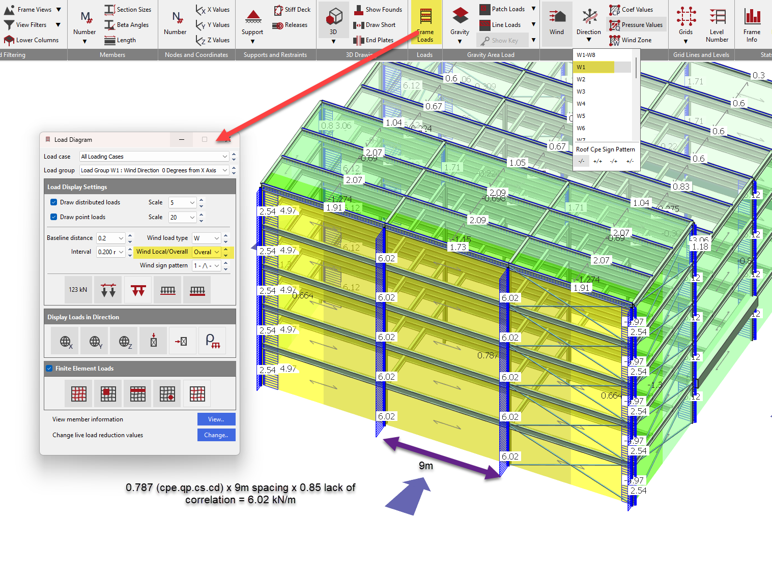
Final wind loading on member can also be viewed in the 'Frame Loads Diagram' by examining appropriate load cases and load groups. Wind Load Type option are available for displaying 'W' external Cpe loads only, 'P, intenral pressure' for Cpe +Cpi external + internal pressure, and 'S, internal suction' for Cpe +Csi external + internal suction. For EC design By choosing the 'Overall' option in the frame load diagram, any lack of correlation and CsCd factors are included in the member loading displayed. Note the 'Overall' will only be displayed where members have been assigned to the EC overall wind loaded member group. In BS design this drop list contains the wind diagonal values assigned in the wind diagonal member groups, in which case the load presented is from the wind load pressure with selected 'a' wind diagonal value, including the 0.85 *(I+ cr) factor
| Location | What You See |
| Panel Pressure (Q) | Raw panel pressure used to generate loads |
| Frame Load Diagram – W | External wind (Cpe only) |
| Frame Load Diagram – P | External + internal pressure |
| Frame Load Diagram – S | External + internal suction |
| Frame Load Diagram – Overall (EC) | Includes Cs·Cd + lack-of-correlation |
| Frame Load Diagram – BS diagonal a | Includes 0.85 × (1 + Cr) |