Beam-to-beam End Plate Simple Connection with Flange Toe Plate
Date: 24/01/2023
Versions: 2023.08 +
Program: MasterKey Connections Design Beam-to-beam End Plate Simple Connection with Flange Toe Plate
Due to popular demand and in keeping up to date with industry practices, Toe Plate Connections are now an option within MasterSeries Steel Connection Design, for Simple Beam to Beam Flexible End Plate Connection Design.
MasterSeries 2023 Simple Connections Design allows you to specify the use of Flange Toe Plates on the outside face of supporting beams, using design principles laid out in the SCI 'Green Book' publications. This technical note elaborates on the underlying principles and considerations designers need to take when specifying a Toe Plate as part of your connection design. The popular Toe Plate Connection solves problems such as ease of installation; avoiding the need to notch beams, and it can be easier for erectors as it eliminates the problem of "swinging-in" (i.e., allowing the 'supported' beam to simply fit between the flanges of the 'supporting' beams).
This technical note was developed, not as a definitive design guide, but to assist with understanding the additional design considerations. Various finite element modelling has been done to demonstrate the effect of different parameters. This is not a scientific research paper, and a full parametric study has not been undertaken.
Additional Design Considerations
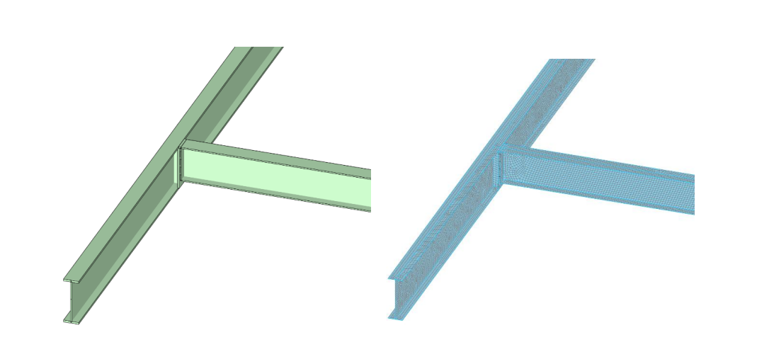
Moving the flexible end plate connection interface from the supporting beam web to the flanges toes of the supporting beam will have an impact on the design of the supporting beam. If we consider the flexible end plate as true pin, i.e. having no rotational stiffness, and the toe plate as a rigid cantilever offset from the web equal to ecc = B/2+ttoe, then an additional torsional moment Mtoe,Ed = ecc * VEd will be developed in the supporting beam, where VEd is the applying supported beam end shear force. ‘I’ sections tend to perform poorly in torsion, with even a small amount of torque moment possibly developing large torsional rotations, which is undesirable. See figure 1 (a).
To avoid this situation, the generally adopted design approach has been to consider the connection between the toe plate and supported beam end plate as a moment connection. This seems counter intuitive since the member design is based on pin ended simply supported beam sections. However, with the moment resisting connection at this connection interface, the torsional rotation of the supporting beam is limited due it is connection with the supported beam, and in effect the supported beam provides torsional restraint to the supporting beam. See Figure 1 (b).
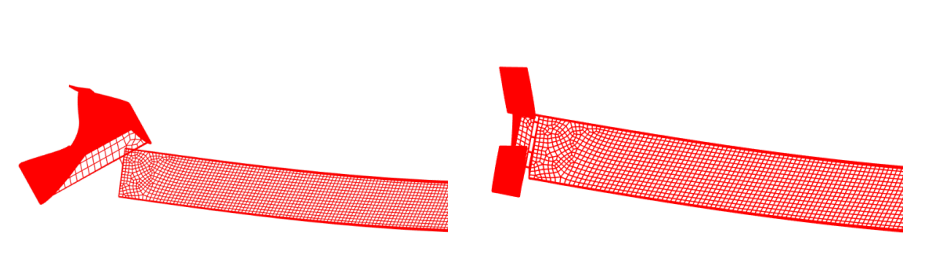
(a) (b)
Figure 1. Deflected shape at 10x magnification. (a) Toe plate with pure pin at supported beam end. Supported exhibits 10.27 degree torsion rotation. (b) Toe plate with 10mm supported beam full depth end plate. Supporting beam is effectively torsionally restrained by the supported beam and exhibits 1.16 degree torsion rotation.
The obvious concern is the supported beam is no longer pinned at the end and may develop hogging moment. The potential for this hogging moment to develop very much depends on how rotationally stiff the supporting beam system is at the connection in the direction of the supported beam major axis.
For cases where the supporting beam is loaded on one side and the connection is not near the end of the beam, it has been demonstrated through finite element modelling that in many general cases the torsional stiffness of the supporting beam is small compared to the major axis stiffness of the supporting beam, and as such the potential to develop any meaningful hogging moment is limited. Hence the supported beam remains effectively simply supported. In this scenario the pin support to the supported beam remains in place at the supporting beam centreline. The moment at the connection design interface is equal to Mtoe,Ed = ecc * VEd, with tension at the bottom on the connection interface. Mtoe,Ed approximates to the moment in the pin ended supported beam at a distance ecc from the node position.
The effect of the supporting beam system on the behaviour of the toe plate connection is considered in more detail further on in this technical note.
Adequate Torsional Restraint to the Supporting Beam
For the moment resisting toe plate connection interface to provide adequate torsional restraint to the supporting beam, it is required to resist the moment Mtoe,Ed , but also have adequate moment-rotational stiffness to prevent in-joint rotation, leading to increased torsional rotation of the supporting beam. The applied moment Mtoe,Ed will generally be much smaller than the moment capacity of the supported beam. The strength capacity of the end plate design may indicate a requirement for a thin plate, however, this will lead to more flexible joint. At this stage it is worth noting that full depth flexible end plates (FDFEP) and moment resisting connections are the same arrangement, with the only requirement on FDFEP being a limitation on the end plate thickness. As referenced in ‘SCI P358 Joints in Steel Construction -Simple Joints to Eurocode 3’, research has been carried on FDFEP and their moment-rotation stiffness effect on the frame design, indicating that where end plate thicknesses are limited, the joint can still be safely considered as a simple connection. The stiffness of a FDFEP cannot be taken in isolation as its ability to act as a simple connection is dependent on the ratio of its stiffness with the stiffness of the supporting system. Where a FDFEP connects to a column, the supporting system has considerable stiffness, therefore the FDFEP will experience higher moment and likely reach its yield point. If the supporting system is more flexible, then the FDFEP may not experience higher values of moment and thus not yield to the same extent, thus retaining its stiffness; such as may be the case with certain configurations in the beam-to-beam toe plate connection.
For a sample configuration of a single sided, centrally located supported beam on a toe plate, finite element modelling of bare steel beams (effect of floor plate not considered) was conducted. All plates were full depth, welded each face. Thickness of the supported beam end plate was varied, whilst the toes plate thickness was kept at a constant of 12mm.
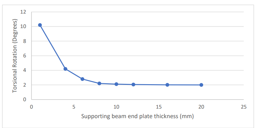
Figure 2. Effect of supporting beam end plate thickness on supported beam torsional rotation.
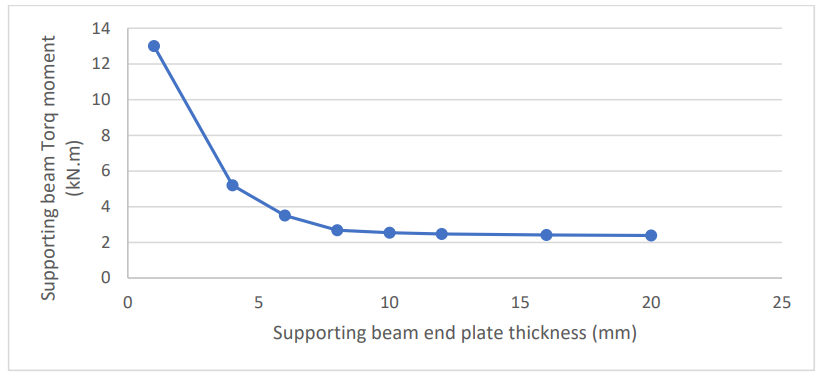
Figure 3. Effect of supporting beam end plate thickness on supported beam torq moment developed.
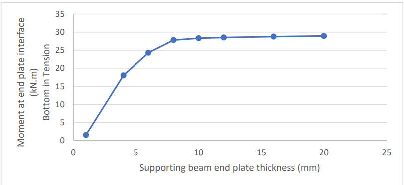
Figure 4. Effect of supporting beam end plate thickness on moment at the plate interface.
In this example an end plate thickness of 8mm was adequate for the connection to act as a rigid moment connection. At this point, the supporting beam rotation and torq moment was reduced to a minimum, and the moment at the end plate interface approached that of Mtoe,Ed, which was 30 kN.m. Even though this would be considered an acceptable full depth flexible end plate (<= 10mm), it provided adequate stiffness in this example to provide torsional restraint to the supporting beam. This is primarily due to the torsional stiffness of the supporting beam being small relative to the connection stiffness. It must be emphasised that this just is one example and not a parametric study.
Beam System Rotational Stiffness
When considering the use of a moment resisting toe plate, careful consideration must be given to the stiffness of the supporting beam system, and its potential to cause hogging moment in the supported beam end. We refer to the ‘supporting beam system’ rather than just the torsional axis of the supporting beam, as the stiffness is dependent on the beam system and not just the isolated supporting beam member. Factors that influence this stiffness include
- Torsional stiffness of supporting beam at point of connection.
- Location of connection along the beam, with connection closer to the support providing increase in supporting beam torsional stiffness.
- The presence of supported beam on the other side of the supporting beam. Where you might have a beam supported on both sides of the supporting beam, then a moment toe plate connection will provide a through beam system, potentially leading to a significant increase in stiffness.
- End warping condition of supported beam, with most simple connection cases providing a more flexible ‘ends free to warp’.
- The profile of any torque moment on the beam will influence the torsional warping stiffness, albeit to lesser extent that other factors mentioned.
- Supported deck system will also influence this stiffness, however this is more difficult to quantify through standard commonly used analysis modelling procedures.
To reiterate, when referring to the supporting beam system rotational stiffness, this is in relation to the major axis direction of the supported beam member, which is also the torsional axis of the supporting beam.
The torsional stiffness of the supporting beam will influence the rotational stiffness of supporting beam system. The torsional stiffness of I sections varies considerably, however where heavier and more torsionally stiff I sections are used, the supported beam will also likely increase in stiffness, hence ratio of supporting beam torsional stiffness to supported beam major axis stiffness is likely to remain low, hence reducing the possibility of producing a supported beam end hogging moment. Where this stiffness ratio increases, e.g., a very small supported beam on a torsionally stiff supporting beam, then supported beam end hogging is possible.
The effect of the position of the supported beam on the supporting beam was considered for another single sided example with a 10mm end plate, with results shown in figure 4. It can be seen that when the beam came within approximately 10 to 15% of length from the supporting beam end, the torq moment increased at an exponential rate. In all cases the torsional rotation did not vary considerably since it was being adequately restrained by the supported beam through the 10mm end plate. It must be noted that even in the case where the support was close to the end and the supporting beam torq was highest, this only represented approximately 5% of the supported beam sagging moment. Furthermore, this small hogging moment was at the supporting beam centreline, however, at the connection interface it had returned to a sagging moment with tension at the bottom. The supporting beam would need to be designed to accommodate these higher values of torq moment.
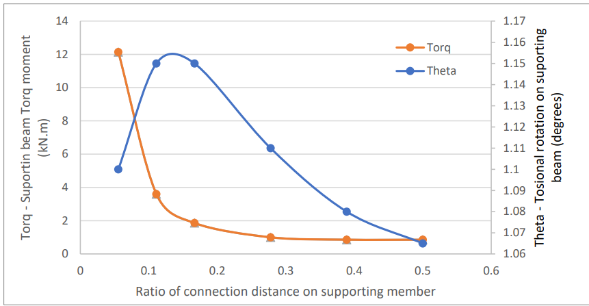
Figure 5 – Effect of position of supporting supported beam along supporting beam on supporting beam torq moment and torsional rotation.
For the case where there is a toe plate connected supported beam either side of the supporting beam at the same location, this creates a ‘through beam’ system, whereby significant hogging is possible. In our FEM this was demonstrated as being approximately 40% of the sagging moment, with smaller end plate thickness relieving this value. This hogging moment is also relieved by the deflection of the supporting beam.
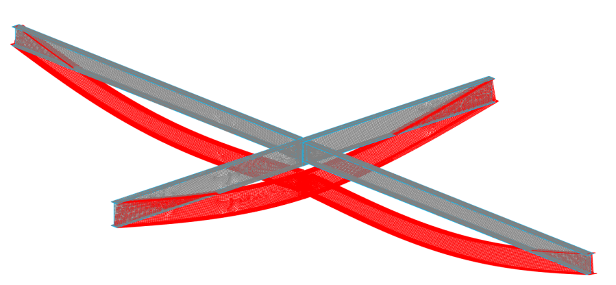
Figure 6. Toe plate moment connection beam on both sides, creating hogging moment at the supported beam end that was 40% of the sagging moment.
Considering the same case with beams on both sides but offset by amount of 0.5m along the supporting beam axis (centrally located on the beam length of 9m), a smaller amount of hogging was still present at the connection interface. With the offset increased to 1m the connection interface returned to a sagging moment. As per the case of the beam connection close to the supporting beam end, for close offsets locally increased non-negligible torq moment was observed in the supporting beam that should be considered in its design.
For the toe plate type connection generally, a hogging moment is to be avoided as this creates compression at the bottom flange of the supported beam, potentially requiring local stiffening of the toe plate and toe plate web stiffener. For the through beam and close offset beam it may be best to avoid the moment design and provide a partial depth end plate on the supported beam end. For the through beam case, modelling with partial depth supported beam end plates (still connected to toe plates) demonstrated no hogging moment, with the beam returning to simply supported as expected. In the through beam case where the forces are balanced, supporting beam torsion was not a concern, however for other cases where partial depth end plates are used, the additional torsional design should be considered in the supporting beam.
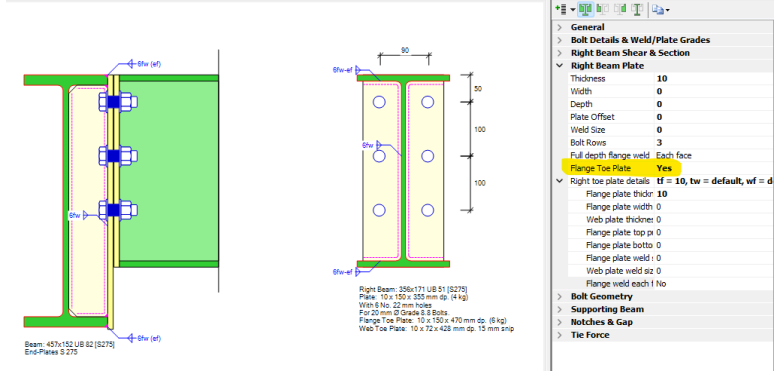
MasterSeries Toe Plate Implementation
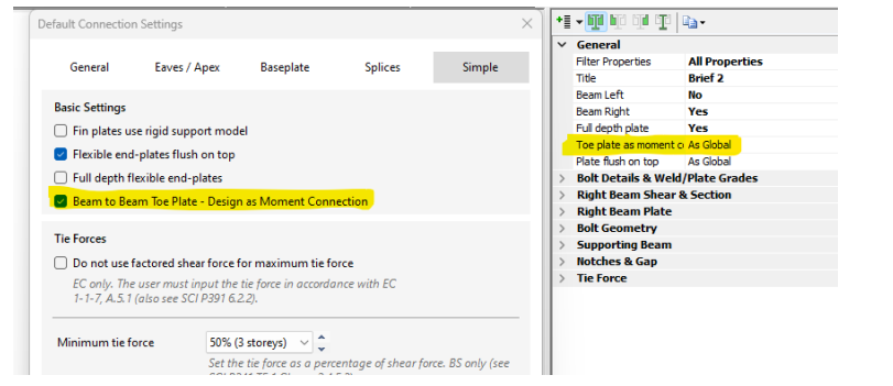
The toe plate option is part of the Beam-to-Beam Flexible End Plate Simple connection type. It is only available for Eurocode design and will not appear for British Standard design. It can be chosen for each supported beam independently from the option below.
As has been demonstrated in many cases the moment resisting toe plate can adequately torsionally restrain the supporting beam, resulting in limited torq moment and torsional rotation, while also ensuring the supported beam remains effectively simply supported. In other cases the toe plate connection can lead to significant supported beam end hogging moment and/or torsion in the supporting beam.
MasterSeries provides two design approaches for the toe plate connection.
- Design as a moment connection for the moment Mtoe,Ed. In this case it is assumed that the supporting beam system is flexible in the major axis rotation direction of the supported beam. Hence the beam remains simply supported, and the supporting beam is torsionally restrained. The end plates for the toe and supported beam end must be full depth with welds on both sides of connected flanges for yield lines to occur along all plate connected edges. The supported beam end plate and supporting beam toe plate are checked independently for the moment and shear force.
- Design as a simple connection for the shear only. In this case the supported beam end plate thickness is checked for the simple connection rules and can also be a partial depth end plate. The design report advises that supporting beam torsional design should be considered for the additional moment ecc x VEd, since the simple connection cannot be assumed to provide torsional restraint to the supporting beam, as per the moment connection. In this approach the endplate interface is considered as a pin, and the moment ecc x VEd is applied to the toe plate web stiffener and the toe plate flange welds. The end plates are designed in the usual fashion for a simple connection, including checks for tying forces.
Information is provided in the design report to this effect in accordance with the engineers chosen design approach. The design approach can be chosen on a connection-by-connection basis or follow a global default setting. It is the engineer’s responsibility to choose the appropriate design approach.
Conclusion
This technical note was produced as an aid to help designers understand the factors involved in the beam-to-beam toe plate connection type. The information may assist with the decision to use a toe plate over conventional supporting beam web connection, and furthermore which design approach may be more appropriate for their given situation. This is not a full scientific research paper and does not involve a full parametric study, and therefore does not offer definite design guidance.