
Stability & Fire Boundary
Elastic Critical Load Factor
The Elastic Critical Load Factor (αcr or Alpha Crit) in MasterPort is a stability check used to assess the frame's sensitivity to second-order effects (deformed geometry).
The Elastic Critical Load Factor check is used to assess whether the portal frame is sway-sensitive (i.e. whether second-order effects are significant). In portal frames it is common for αcr to be ≥ 10, so the check often passes without issue; however, lower values can occur in more flexible frames or where secondary/non-portal members influence the global stiffness. This value determines whether a first-order analysis is sufficient or if the structure requires a second-order (P-Delta) analysis to account for sway effects.
How αcr is calculated in MasterPort
This is handled in the 📄 General tab – Setup Overview. MasterPort can determine αcr in two ways:
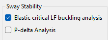
☑️Checked: Elastic Critical LF Buckling Analysis
⏹️Unchecked Sway Deflection Method (Approximate)
⏹️Sway deflection method (default approach)
MasterPort automatically generates Sway Stability load cases which apply Equivalent Horizontal Notional Loads (EHNL) in the plane of the portal frame only. This means the check is inherently focused on the in-plane portal stability (out-of-plane instability is usually not critical for portal frames because rafters/columns are typically restrained by purlins and side rails).
'Sway Stability' loading cases are automatically generated that include equivalent horizontal notional loads only, producing the necessary deflections on which the empirical approach is based. The sway deflection method is based on the maximum h/200*δH,HNL from all vertical members.
Omitting minor vertical members (sway method only)
If parapets/canopies or other minor vertical members are present and you do not want them to influence the sway check, you can omit them from the sway assessment: place the cursor in the large box at the bottom of the screen, then click the members to omit. Their member numbers will be listed and excluded from the sway calculation.

For Eurocode design, when the elastic critical load factor is determined using the sway deflection method, SCI P399 section 7.5 is used
Sway critical factor (based on notional-load sway): αcr,s= h / 200δH,HNLh
and 7.6.1 is used to account for significant rafter axial force adjustment.
Rafter axial force adjustment (where rafter compression is significant): αcr,s,est = 0.8 (1− NEd / Ncr ) αcr,s
For in depth details of the elastic critical load factor check see the relevant sections in the
- MasterFrame manual 📄 Elastic Critical Load Factor - Buckling Analysis 📄 Elastic Critical Load Factor
- MasterKey Steel Section design Manual 📄 Elastic Critical Load Factor Brief 📄 Elastic Critical Load Factor Brief

☑️Buckling analysis (eigenvalue) method (optional)
You can choose to determine αcr using a buckling analysis (enabled via the relevant option in the MasterPort inputs). When running buckling analysis in MasterPort, this is treated as a special portal-frame case:
Only the main portal in-plane major-axis geometric stiffness contributions are modified/considered for the buckling check.
This is applied only to members carrying the MasterPort UT naming/attribute convention, for example:
UT (Rafter…)
UT (Column…)
UT (Lean-To Beam…)
UT (Lean-To Column…)
UT (Prop…)
UT (Mezzanine…)
These UT names/attributes are applied automatically by MasterPort.
MasterPort vs MasterFrame Buckling Analysis Method
For portal buildings in MasterPort we are generally interested in the in-plane portal αcr. Out-of-plane buckling is typically restrained by purlins/side rails and is checked separately via member design and restraint definitions rather than through a global eigen-buckling mode.
MasterFrame buckling analysis, by contrast, considers all members and typically in both major and minor axes, and it does not automatically account for design-time lateral restraint. In MasterFrame it is therefore common engineering practice to include at least some representation of the lateral restraint system (or suitable boundary conditions) if you want eigen-buckling results to reflect restrained behaviour.