Elastic Critical Load Factor Brief
The Elastic Critical Load Factor brief presents the calculation of the αcr (Eurocode) or λcr (British Standard) sway mode elastic critical load factor. From this value it can be determined whether or not the structure is sensitive to second order geometric nonlinearity effects, and thus informing if a P-Delta 2nd order analysis is required.
From BS EN 1993-1-1:2005 the calculation of αcr is determined by either the approximate method given in Clause 5.2.1 (4) ,
αcr = (HEd / VEd) * ( h / δH,Ed)
Where:
- HEd is the total design horizontal load, including equivalent horizontal forces, transferred by the storey (storey shear force)
- VEd is the total design vertical load on the frame, transferred by the storey
- δH,Ed is the horizontal displacement as the top of the storey, relative to the bottom of the storey.
- h is the height of the storey under consideration
From BS 5950-Pt1:2000 a similar method is give in Clause 2.4.2.6,
- λcr = h/200*δH,HNL
Where:
- δH,HNL are horizontal storey height displacements from the from the application of 5% of vertical loads as Horizontal Notional Loads (HNL) loads acting alone. These load cases can be generated in the model and are termed Sway Stability cases. Multiple Sway Stability cases are usually creating for HNL's in different horizontal directions.
Assessing
The above assessment is for the sway mode elastic critical load factor and is carried out on all vertical members in the model to determine the most critical (lowest) αcr\λcr sway mode elastic critical load factor. This is done on load case by load case basis and results presented for each case. Not all load cases will be assessed for the elastic critical sway mode load factor. For Eurocode it assessed for all ultimate load cases that have factored loading + EHF (equivalent horizontal forces) are applied. For BS5950 it is the Sway Stability - HNL alone load cases. In MasterSeries 2025 control over which load cases are used for this assessment is given in the MasterFrame area where the load case are HNL/EHF applied.
Alternatively, the Elastic Critical Load Factor can be determined from the Buckling Analysis method from MasterFrame for any load case where this 2nd order analysis option has been activated. The Elastic Critical Load Factor will indicate the method used to determine it in the results area of the brief. 📄 Elastic Critical Load Factor - Buckling Analysis
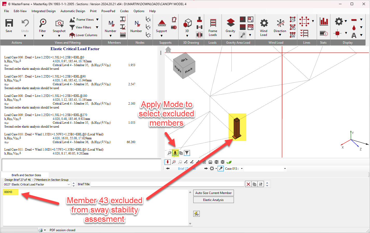
When the brief has been applied to a model, the initial screen is as shown below.
Briefs and Section Sizes
The Briefs and Section Sizes tab allows the user to control which elements of any model are considered as part of the Elastic Critical Load Factor calculation. While in 'Apply' graphical select mode, members can be selected to be excluded from the calculation by using the mouse pointer and selecting the member(s) to exclude graphically. The member number(s) will appear in the rectangle below the briefs and Section Sizes heading. A typical use of this feature would be to exclude parapet members, which may be relatively more flexible than the main structural members and so could potentially lead to the return of a lower αcr value. Th vertical member exclusion will only affect the elastic critical load factor determination based on the sway deflection empirical design code method, and will not affect the elastic critical load factors derived from a buckling analysis.