General tab – Setup Overview
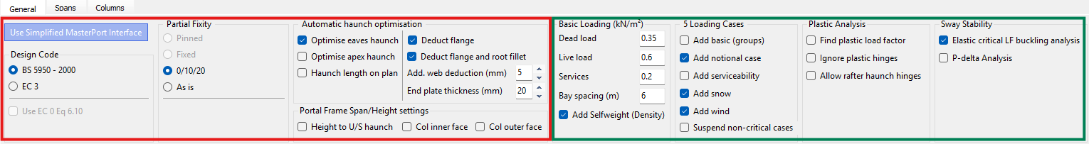
Use the General tab to define the core design settings, base fixity, haunch strategy, basic gravity loads, load combinations, analysis method, and sway stability options.
LHS Options
RHS Options
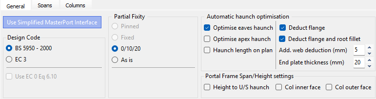
Design code
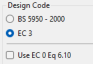
Select Eurocode or British Standard.
For Eurocode, the default is 6.10a/6.10b; you can switch to 6.10 if preferred.
Partial Fixity (Base Fixity presets)
Simplified Interface Settings

Pinned: Only Available outside of the Simplified MasterPort Interface aka 'Further Editing'
Fixed: Only Available outside of the Simplified MasterPort Interface aka 'Further Editing'
0/10/20 as a common preset:
ULS: bases treated as pinned (0%).
SLS: 20% base fixity to reduce deflections (with an intermediate 10% where applicable).
As Is: uses base fixities defined on the Columns tab (and elsewhere) without overriding.
Under Supports and Restraints within the top toolbar, you can also display member releases while creating members to visualise end conditions.
'Further Editing' Fixity Settings

Pinned
Fixed: You can set the Base Partial Fixity in the box below.
Drop Down List: Shows the Gable / External / Internal Columns
As Is: uses base fixities defined on the Columns tab (and elsewhere) without overriding.
Base Partial Fixity: Set % fixity for Fixed Based
Blue squares at column bases denote partial fixity.
 turns the supports on / off for each support on the graphics
Automatic haunch optimisation
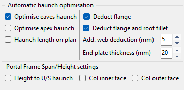
The program computes the maximum haunch depth consistent with the rafter section and places a node where the haunch underside aligns with the column flange.
.png)
Notation: Hd_perp = D − T − r (perpendicular haunch depth).
Options include removal of flange, root fillet, and web allowances; specify end plate thickness.
Eaves and apex haunches can be auto-optimised from the rafter section.
Optimise Apex/Eaves Haunch
Haunch depths are calculated automatically.
Haunch Length on Plan
Deduct Flange / Flange and Root FIllet
Add Web Deduction (mm)
End plate thickness (mm)
Portal Frame Span / Height Setting
Geometry measurement options
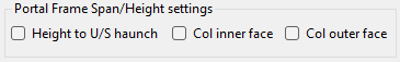
On plan: measure haunch length from column centreline in plan (not along the rafter slope).
Height to Underside of haunch
Not CL–CL intersection.
Col Inner Face
Span between inner faces of columns (instead of column centrelines).
Col Outer fac
Span between outer faces of external columns.
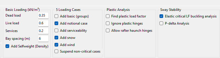
Basic Loading (Gravity)
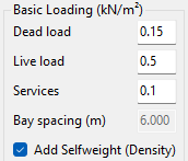
Dead Load (G)
in (kN/m²).
Lives Load (imposed/services (Q/Svcs)
in (kN/m²).
Services
Dead and services are separate so you can consider G + wind uplift without services.
Bay spacing
Read from geometry; area × spacing produces member line loads for analysis.
Load cases and combinations
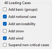
Before analysing the portal building ensure that all the appropriate ultimate and service load case options on the General tab have been included. Activating an option to show any type of loading, for example, Draw Snow Load, will show the total number of load cases that have been generated for combinations of dead, live, wind, snow and crane loads.
Add Basic
Adds single load cases for each load (i.e. D1, D1+D2, L2, W1, W2, W3....)
Add Notional Case
Will add notional load case on top of all Dead plus Live cases
Add Serviceability
Add service (SLS) companions for each ULS case.
Add Snow
Include snow combinations where relevant.
The software automatically calculates the required snow loads and generates several specific snow load cases for the analysis. These load cases typically include:
- L0: A blanket Uniformly Distributed Load (UDL) over the complete structure.
- L2: Asymmetrical UDLs, such as snow on one side only or on the leeward sides of the portal spans.
- L3 - L5: Drift load conditions, such as valley snow drifting, drifting against parapets, or other abrupt changes in height.
Add Wind
Tick to include/exclude wind loads from automatic generation.
Suspend Non-Critical Cases
After an initial run, analyse Envelope (critical) cases only to speed iterations.
Complex 3D frames can easily exceed ~200 load cases.
Plastic Analysis options
Read More here: 📄 Analysis of the Frame
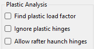
Find Plastic Load Factor
- Runs a rigid-plastic (mechanism) analysis and incrementally amplifies the applied actions until a plastic collapse mechanism forms.
- The software identifies hinge formation at the usual locations (typically eaves/haunch ends and apex) and reports the plastic load factor λ_pl at collapse.
The hinge location and plastic load factors will be given in the graphical output results area, if hinges form in that loadcase.
Ignore Plastic Hinges
Forces a purely elastic global analysis and suppresses plastic hinge formation, even if sections would yield locally.
For serviceability studies (deflection/drift) or comparison runs.
When you want a conservative global response without plastic redistribution.
When setting up restraint and bracing before moving to a plastic verification.
Allow rafter-haunch hinges
Permits plastic hinges to form at the haunch ends/eaves (and at the apex, where relevant). This reflects the intended plastic mechanism of a portal frame with haunched rafters: hinge at the underside of the haunch/eaves plus an apex hinge under gravity-dominated combinations.
Standard plastic portal design assumes hinges at eaves and apex; enabling haunch hinges aligns the analysis with that target mechanism.
Needed when exploring haunch geometry (length/depth) and verifying that the hinge forms where expected without premature LTB.
Note - this will create additional nodes and therefore increase the member number in the frame.
Read more 📄 Understanding Plastic Behaviour and 📄 Automatic Design Procedure
MasterPort Plastic vs. Elastic Analysis
Read more in our Guidance Note here 📄 Plastic Analysis Options – Quick Decision Flow.
A frame can be Analysed using elastic or plastic analysis, when you click on Analyse.

Sway stability
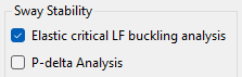
Elastic Critical Buckling Analysis (Elastic Critical Load Factor / λcr)
This option solves an eigenvalue buckling problem around the first‑order state and reports αcr (or λcr in BS), the factor on loads to reach elastic instability.
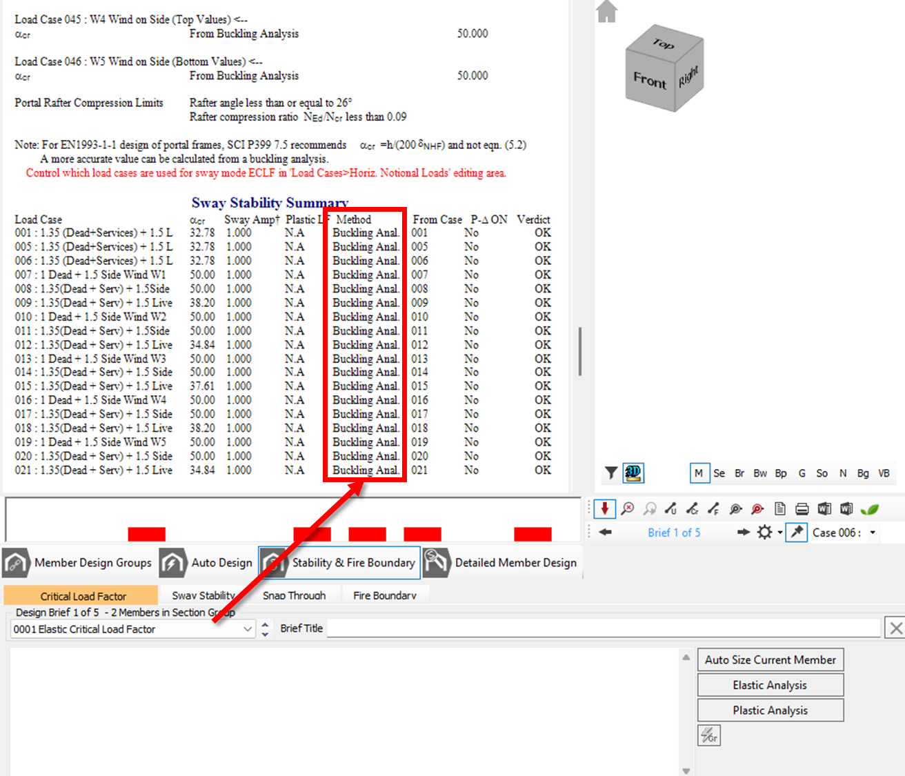
Results can be viewed from within the Steel Design module under 📄 Stability & Fire Boundary - Elastic Critical Load Factor
Read More here: 📄 Elastic Critical Load Factor Buckling Analysis in MasterPort
- ☑️Checked: Elastic Critical LF Buckling Analysis ON
The Buckling Analysis method is used (recommended for more accurate values of αcr for Portals). This computationally determines the elastic critical load factor by rigorously assessing the frame's buckling mode shapes. Read More here: 📄 Elastic Critical Load Factor Buckling Analysis in MasterPort - Results can be seen in
- Bucking Mode Shape can be seen within the Graphical Analysis Output
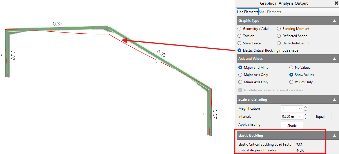
- αcr values can be found within the Steel Design Module > 📄 Stability & Fire Boundary - Elastic Critical Load Factor
- Bucking Mode Shape can be seen within the Graphical Analysis Output
- ⏹️Unchecked Elastic Critical LF Buckling Analysis OFF:
The 'Sway Stability' Equivalent Horizontal Notional Load (HNL) method is used. This evaluates the αcrit value using the standard Eurocode equation based on the horizontal movement of the structure relative to its story height under applied loads. Read More here: 📄 Elastic Critical Load Factor Buckling Analysis in MasterPort - Results can be viewed within Steel DesignModule > 📄 Stability & Fire Boundary - Elastic Critical Load Factor
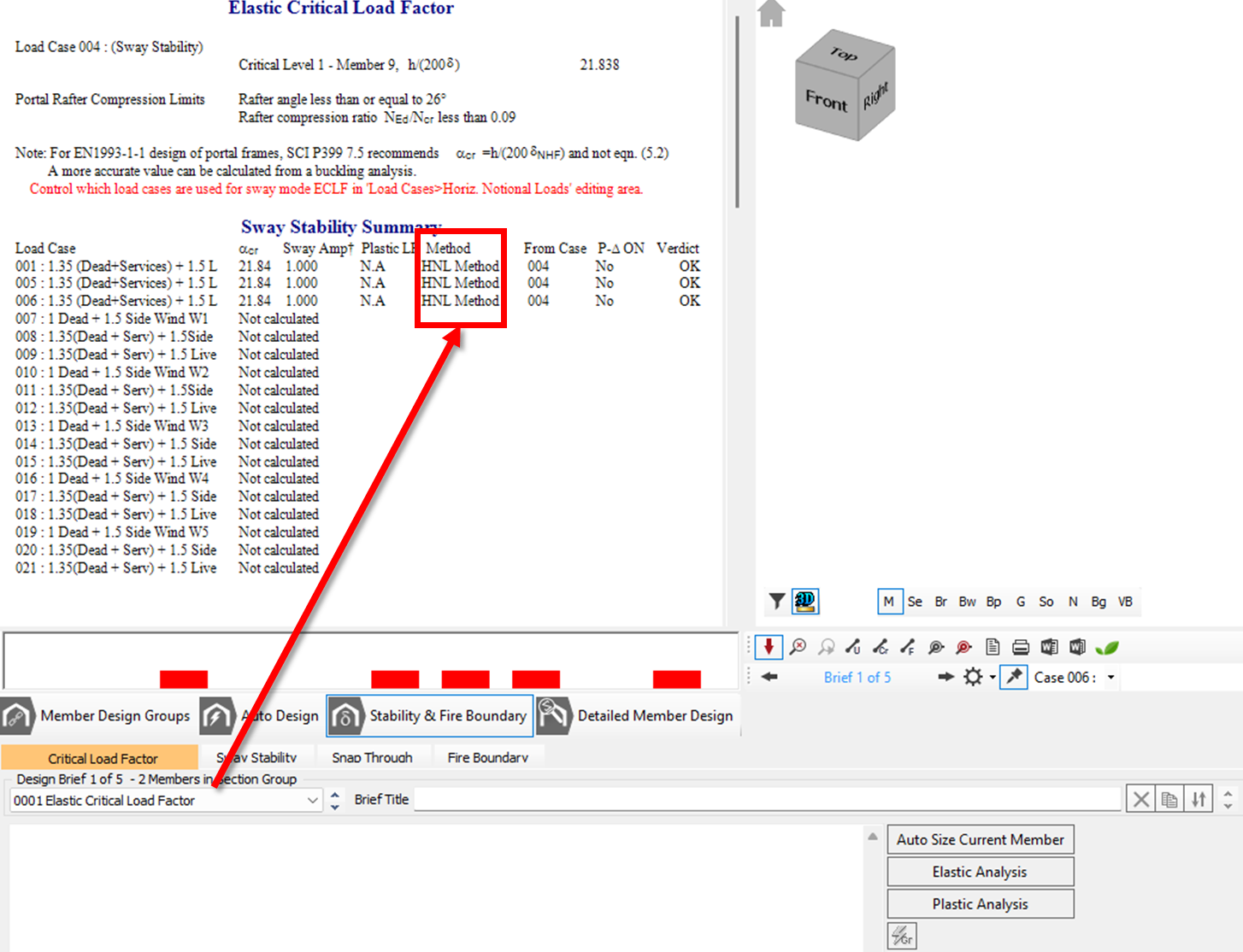
- Results can be viewed within Steel DesignModule > 📄 Stability & Fire Boundary - Elastic Critical Load Factor
P‑Delta Analysis (global second‑order)
Read More here: 📄 Analysis of the Frame
Use for member design and deflection checks. Compare first-order vs P-Delta to see the amplification in moments/drifts on governing combos.
Re‑analyses with geometric stiffness so that axial force × lateral displacement feedback (P‑Δ) is included.
Produces amplified moments/deflections directly for design.
Sensitive to imperfections (global sway imperfection / notional loads) and fixity/restraints.
Recommended workflow
Scan λcr first to identify the governing load patterns and any unexpected sway modes.
Design to P-Delta results for those governing combinations (member utilisations, drift/serviceability).
If λcr is low, consider stiffness upgrades (sections/haunch/base fixity/bracing) and re-run both.
Old Manual Entry
General tab
.png)
On the General tab, you can set up the basics for the portal frame. This commences with which design code is to be used - British Standard or EuroCode. By default the EuroCode will use equations 6.10a and 6.10b. You can change this so it uses 6.10 instead should you wish.
The base partial fixity can be specified. This is normally accepted as 0/10/20 meaning that in ultimate cases the base fixity is zero, ie, pinned for design, but 20% fixity for the service cases to allow a reduction in the frame deflection. The bases can be set to fully pinned or fixed if that is how you wish to consider your frame. The "As Is" option allows the column base fixities, specified in the Columns input tab and elsewhere, to take precedence.
Blue squares at the bottom of a column are used to denote base partial fixity.
When creating members, it is possible to explicitly turn on the display of releases so that you can see the member conditions as they are specified.
Automatic haunch optimisation - the eaves and apex haunches can be set to be automatically optimised based on the rafter section size. The haunch usually has the flange removed (deducted) and possibly the root fillet too. Additional web can also be removed. The end plate thickness is also specified. Based on all these criteria the program calculates the maximum section depth of the haunch based on the rafter section size. A node is placed on the column at the point where the haunch bottom flange coincides with the column flange.
Hdperp = D -T-r
- On plan - measure haunch length on plan from centreline of column, as opposed to the default of measuring it up the rafter slope.
- Underside - measure column height to underside of haunch, as opposed to the default of the intersection of the column and rafter centrelines.
- Clear span - measure span between inner faces of columns, as opposed to the default of the column centrelines.
- Outer face - measure the overall span between the outer faces of the external columns.
.png)
The basic dead, live and services loading is included as an area plan load in kN/m2. Note that the dead and service loadings are separated to allow for a minimum loading of dead plus wind uplift without any service loading being included. The frame spacing is automatically picked up from the frame geometry. These are multiplied together to give a line load on the members ready for analysis.
A combination of all the necessary load cases can be added by ticking the appropriate boxes. You can add or omit the wind and snow loading from the automatic generation of load cases, add service cases for each ultimate load case, include P-delta analysis in all load cases and use only the envelope (critical) load cases for analysis. The last option only becomes active after at least one analysis cycle has been completed for all load cases, from which the critical cases can be detected. The notional cases can be included as well as basic cases for each load group. In a typical 3D frame it would not be uncommon to have as many as 200 load cases.
A frame can be analysed elastically or plastically as desired. In plastic analysis there are options to find the plastic load factor, ignore plastic hinges or allow rafter haunch hinges to possibly form.
For sway stability the default is to use the horizontal notional loads to obtain the elastic critical load factors. Alternatively you can use the buckling analysis method instead.