Auto Design Tab (and Procedure)
An auto size design brief must exist before automatic design procedures become available. To activate the automatic design controls, either select the Automatic Design from the Edit-View menu, or click on the auto design icon  from the MasterPort toolbar.
Before commencing with automatic design it is essential that the design briefs and associated member design groups are satisfactory. The default design briefs and member groups are suitable for standard portal frames, such as those entirely created from the portal frame generation template. Where the portal frame is more complex, the engineer must amend the groups and/or briefs as described above.

Auto Design Section Size Settings
Members are auto sized
.png) according to their design group or
according to their design group or.png) the whole frame auto sized at one time
the whole frame auto sized at one time
The auto size feature checks all members in a group and searches for either:
- The lightest and then stiffest section in the same weight, or
- The shallowest (smallest depth)
.png)
Members can be auto sized either elastically or plastically. In the elastic approach members are auto sized to remain within their local moment capacity, preventing the formation of any plastic hinges.
The plastic sizing approach attempts to create up to 40% over-stressing below the haunch node in the exterior columns to facilitate the formation of plastic hinges.
The auto size selection is also dependent on the specified lateral restraint. You can decide whether to have fewer restraints, giving a slightly heavier section, but less fabrication costs, or use a lighter section available but possibly more restraints required. Also,
- If an equal spacing has been specified the sections are sized to satisfy local moment capacity checks only. By defining an equal spacing, MasterPort assumes the engineer intends to adequately laterally restrain the member group in the next design step.
- If the value of equal spacing is set to zero, the sections are sized to satisfy all Axial with Moment design checks, since it is assumed that intermediate lateral restraints will not be provided.
A common section size is determined for all members in a group.
Auto Restraining of Members
The auto restrain features are:
- Auto Restrain ALL;
.png) and
and - Auto Restrain Current Group
.png)
These take the specified equal spacing and tests for failures in each portion. In portions where the restraints are inadequate, their spacing is modified and stored. All members in a group are checked with a single arrangement of restraints being applied to the group.
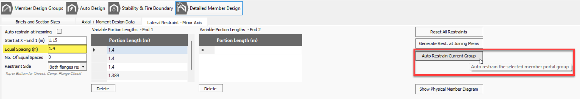
If an Appendix-G stability check has been applied to the active group auto restrain continues to determine the optimum location of torsional stability stays. Note: If an equal spacing value has not been defined the auto restrain function is disabled.
Step by Step Auto Design
The step by step auto design approach provides the user with more control over decisions the program has made. After each step the user may decide to alter information before proceeding to the next one.
Auto Sizing Members
- Elastic Analysis: Performs a pure elastic analysis based on the current section sizes, removing any plastic hinges previously formed.
.png)
- Auto Size Current Group: Auto sizes all members in the current group
The current group members are highlighted (in black) in the frame graphics area. At this stage the engineer may wish to preview the suitability of selected sections before continuing. - Select the next member group by clicking on any of the associated members in the frame graphics area. Repeat step 2 for all member groups
- Plastic Analysis: Once all the groups have been sized perform a plastic analysis.
.png) This detects the formation of plastic hinges, and calculates plastic moment redistribution. This is recommended even while sizing elastically to confirm that the frame is elastic, as intended.
This detects the formation of plastic hinges, and calculates plastic moment redistribution. This is recommended even while sizing elastically to confirm that the frame is elastic, as intended.
Important note:- The automatically selected section sizes are dependent on the bending moments, which are influenced by the stiffness of the original section sizes. Where the difference in stiffness of the altered and original section sizes is considerable, the altered section sizes may not be the most suitable for continuing with a plastic analysis. This situation is mitigated by conducting steps 1 to 3 twice before performing plastic analysis.
Auto Restraining Members
- Activate an Axial with Moments, or Appendix-G design brief. The member design group associated with the brief will be activated.
- Auto Restrain Current Group: This function is available in either the Lateral or Torsional Restraints tab. In the lateral restraints tab the control will perform both lateral and torsional stability auto restraint, whereas in the torsional restraints tab, the same control carries out torsional stability auto restraint only.
After auto restraining the engineer has the option to rationalise the lateral restraint and stay arrangements for the current group. An alternative initial value of equal spacing may yield a more economical design. - Repeat steps 1 and 2 for additional member design groups.
Full Auto Design
Both the auto sizing and auto restraint procedures outlined above can be conducted automatically using two simple commands:
- Auto Size All: Auto size all member design groups as described above.
- Auto Restrain All: Auto restrain all member design groups as described above.
The fully automatic design functions provide a powerful tool for the complete design of a portal frame by a few clicks of the mouse button.
To minimise the effects of large stiffness ratios between original and altered section sizes, two cycles of auto size are automatically conducted. The engineer has less control over the full auto design process, however in most situations of standard portals, a realistic and economical design will be produced.