Concrete Encasement
Concrete encasement may be specified for steel members where a concrete casing is provided around the steel section. The current implementation considers concrete encasement around steel members only and allows a modification to the member's axial capacity and lateral torsional buckling (LTB) resistance.
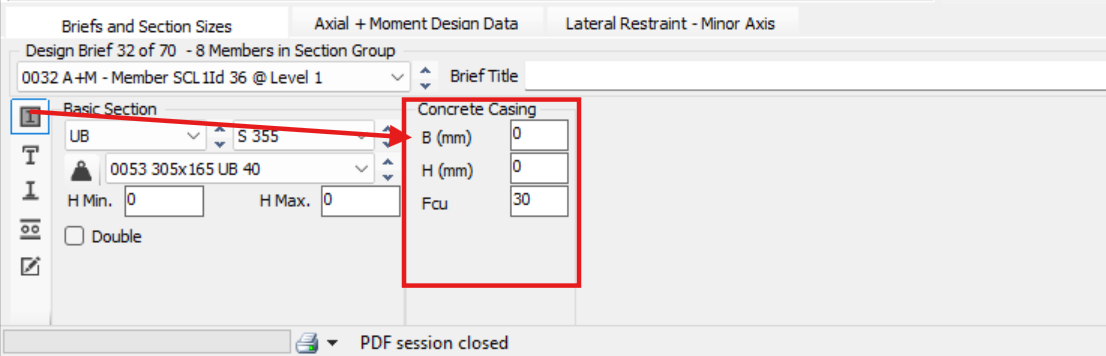
When concrete encasement is enabled, the following properties become available for definition:
- Concrete casing width, B
- Concrete casing height, H
- Concrete strength grade
Effective Concrete Cover
For the encasement to be considered effective, a minimum concrete cover of 50 mm must be provided around the steel section.
If B or H value are entered which do not provide the 50mm minimum cover the casing dimension are automatically increased to provide this cover, rounded up to nearest 5mm. In this way nominally small values may be entered and will dynamically change as the section size changes
At steel design time, if B or H values are entered which exceed 75mm cover the casing dimension are automatically decreased to provide a maximum of 75mm cover, rounded down to nearest 5mm. The larger input dimensions are used in structural analysis section properties.
Concrete Casing Properties
Global concrete casing properties may be defined within MasterFrame using the Concrete Casing Properties settings.

Structural Analysis
The casing dimension (minimum 50mm cover) along with the specified Concrete Casing E modulus kN/mm² value are used to increase the steel sections major and minor axis inertia (second moment of area) values.
The self weight of casing is added to the member self weight.
Design Methodology
MasterSeries continues to adopt the BS 5950-1:2000 Clause 4.14 approach for concrete-cased members. The provisions of EN 1994-1-1:2004 (Eurocode 4), Section 6.7, have not been implemented.
While there is no known Non-Contradictory Complementary Information (NCCI) or supplementary guidance explicitly permitting the use of the BS 5950 methodology in Eurocode design, simple comparative studies have shown the BS 5950 approach to be considerably more conservative than the more complex Eurocode 4 method.
Historically, the BS 5950 approach has been retained due to:
- Its conservative nature.
- Its simplified calculation procedure.
- The avoidance of the full axial force–bending moment interaction analysis required by Eurocode 4.
Under the BS 5950 methodology, the concrete contribution is ignored when determining bending resistance, except for its effect in enhancing the section radius of gyration used in the calculation of lateral torsional buckling resistance.
Composite Action and Load Transfer
BS 5950 provides limited guidance regarding load transfer between the steel section and surrounding concrete, stating only that the steel should be unpainted and free from oil, grease, and other contaminants.
In contrast, EN 1994-1-1 Clause 6.7.4(3) provides more detailed requirements for the transfer of load between steel and concrete. The adequacy of load transfer depends on the end detailing provided. Where a fully compressed end plate is not present, additional shear connection may be required to ensure composite action between the steel and the concrete casing.
Users should ensure that appropriate detailing is provided where reliance is placed on the concrete encasement.
Maximum Effective Length for Concrete Encasement
The beneficial effects of concrete encasement are only considered where the member effective length does not exceed a limiting value.
A maximum casing effective length, Le,max, is determined in accordance with BS 5950-1:2000 Clause 4.14.1(i):
The max casing Le = min(40 x Bc, 100 x  , 250 x min(ry, rx)) mm units.
where:
- Bc = concrete casing width
- Hc = concrete casing height
- rx, ry = radii of gyration of the uncased steel section
All dimensions are in millimetres.
If either:
- Lex > Le,max, or
- Ley > Le,max
then the concrete encasement is deemed ineffective and is ignored in the design calculations.