CAD Layer
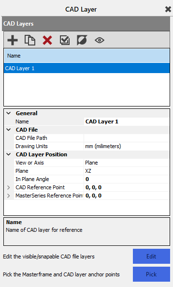
The CAD Layer functionality in MasterSeries allows you to import external CAD drawings (such as architectural wall layouts) to serve as a high-accuracy reference overlay within the MasterFrame modelling environment. This layer is used primarily for tracing structural members, gridlines, and loads directly over the original design artifacts.
 #
Viewing Imported CAD Data
Imported CAD wireframe drawings are treated as a non-structural background layer. When a CAD file is imported, MasterSeries automatically places different CAD layers into separate viewing groups, allowing you to selectively hide or display specific parts of the architectural drawing while you work. This provides a clean workspace where you can see the analytical centre lines of your members superimposed over the physical dimensions of the architectural plan.
Advanced Snapping and Accuracy
The primary benefit of the CAD Layer is that it provides snapping artifacts to assist in the rapid generation of the structural model.
- Standard Snaps: You can snap directly to CAD lines, endpoints, and intersections to ensure the model matches the architectural intent exactly.
- Offset to Perpendicular Snap: To facilitate placing members in the centre of architectural elements, you can use the offset to perpendicular to line snap setting. For example, if an imported CAD drawing shows a wall that is 0.3 metres thick, you can set a snap offset of 0.15 metres to perfectly centre a new structural beam within that wall as you trace it.
- Intersection Snaps: As you move the cursor near CAD lines, the system provides intersection snaps between the cursor's path and the adjacent CAD lines, ensuring precise placement even for complex, non-orthogonal geometries.
Navigation within the CAD Layer
Navigation while using a CAD Layer follows standard industry practices to ensure a smooth transition from CAD packages:
- The Navi-kit: Use the 3D navigation cube to quickly switch between front, side, and plan views. Clicking on the corners or faces of the cube will rotate the structure to that specific orientation.
- 3D Orbit: Standard navigation is performed by holding the Shift key and the middle mouse button to rotate the structure.
- Home and Zoom: Use the Home icon to instantly return to the full frame view and zoom to the model's extents. The Filter (zoom window) tool allows you to isolate and magnify specific sections of the CAD overlay for detailed tracing.
Recording Views via Snapshots
Once you have aligned your structural model with the CAD Layer, you can save specific views as Snapshots. Unlike a standard frame view, a Snapshot is an absolute record of the view's position, orientation, and specific annotations. These are particularly useful for report generation, as they allow you to reproduce the exact graphical state of the structure—showing the traced model over the reference layer—in your final documentation.
You can read more here: 📄 Importing CAD Layers