Portal Frame Analysis Design Process
The portal frame design process in MasterPortPlus is the same as MasterPort, with additional management facilities made available.
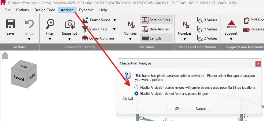
To enter MasterPort Design, the portal frame must first be analysed. There are several options and considerations which we will cover in this article.
In MasterPort, a portal frame can be analysed either elastically or plastically as desired.
Elastic Critical Load Factor (αcr) and when to use P-Delta
The Elastic Critical Load Factor (αcr) and P-Delta analysis are both tools used to assess and accommodate second-order geometric non-linear effects (where the change in geometry of a structure due to loading affects its behaviour). However, the application and limits of these methods differ depending on whether you are conducting an elastic or a plastic analysis.
αcr is a screening value that indicates proximity to global elastic instability. In EC3 practice:
| Analysis Methodology | αcr Value Range | Required Analysis Option |
| Elastic Analysis | αcr≥10 | First-Order Elastic Analysis: The effects of deformed geometry can be safely neglected. |
| Elastic Analysis | αcr<10 | Second-Order Elastic Analysis: Second-order effects are significant and must be accounted for. You can either carry out a full P-Delta analysis or use a modified first-order analysis (such as the amplified moment method). |
| Elastic Analysis | αcr<3.0 | Full Second-Order Analysis: Simple amplification is no longer sufficiently accurate, so a full second-order (P-Delta) analysis must be utilized. |
| Plastic Analysis | αcr≥10 | First-Order Plastic Analysis: The effects of deformed geometry can be safely neglected. |
| Plastic Analysis | 5≤αcr<10 | First-Order Plastic Analysis (Conditional): For portal frames subject to gravity loads, second-order effects can be neglected if specific geometric conditions are met, such as the span not exceeding 5 times the mean column height. |
| Plastic Analysis | 3.0≤αcr<5 | Second-Order Elastic-Plastic Analysis: Second-order effects must be accounted for. In MasterPort, this can be accommodated using simple design rules based on the Merchant-Rankine reduction method. |
| Plastic Analysis | αcr<3.0 | Full Second-Order Elastic-Plastic Analysis: Standard simplified methods like the Merchant-Rankine formula are not applicable, requiring advanced full second-order elastic-plastic analysis software. |
Elastic Analysis
The Elastic Analysis function performs a pure elastic analysis based on your current section sizes, fixities, restraints and load cases.
Elastic Analysis of the Frame
The Elastic Analysis option removes any plastic hinges (and any plastic moment limiting/redistribution effects) that may have been previously formed during prior analysis iterations. MasterPort then produces standard first-order results (forces, moments, reactions, deflections) for each load case.
Auto Sizing of Elastic Members in the Steel Design Module
If you utilise the auto-size feature under the elastic approach, MasterPort will size the members to remain strictly within their local moment capacity, preventing the formation of any plastic hinges.
Elastic Critical Load Factor (αcr) for Elastic Analysis
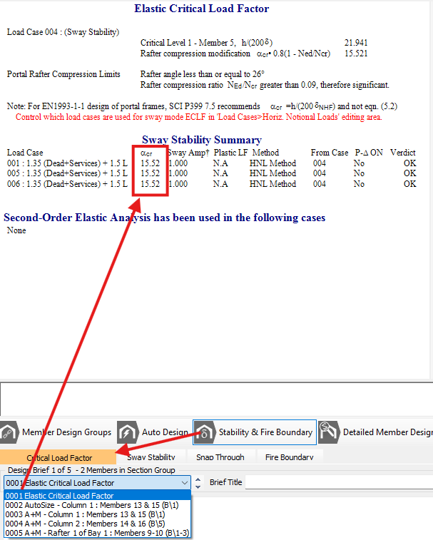
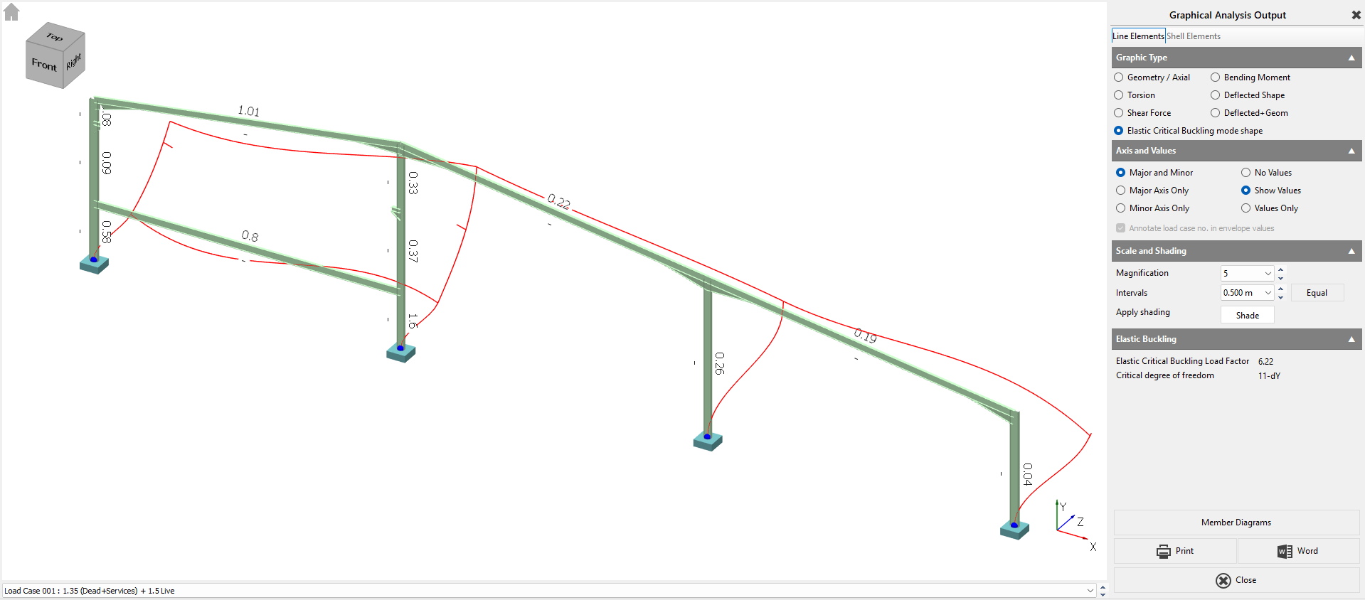
Alongside standard elastic checks, MasterPort evaluates the Elastic Critical Load Factor (αcr) to assess your frame's sensitivity to second-order effects. For considerations regarding portal frame sway stability and realistic αcr assessments, please refer independently to SCI P399.
In a first-order elastic analysis, the effects of deformed geometry can be safely neglected if your calculated αcr≥10. If the value falls below 10, the frame is deemed sensitive to second-order effects, and a P-Delta (second-order) analysis must be utilised.
You can view these results under 📄 Stability & Fire Boundary - Elastic Critical Load Factor.
The software
If P-Delta is enabled separately, the elastic run is followed by a second-order elastic solution for each load case (still with no plastic hinges). This P-Delta (second-order) analysis continually reanalyses the frame under each load case until it stabilises, explicitly capturing the changing stiffness due to deflections.
Plastic Analysis
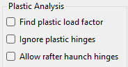
You can read about the various options for Plastic Analysis within the📄 General tab – Setup Overview
Plastic Analysis of the Frame
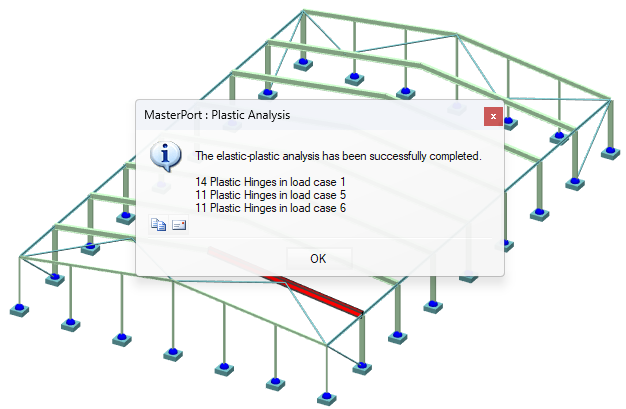
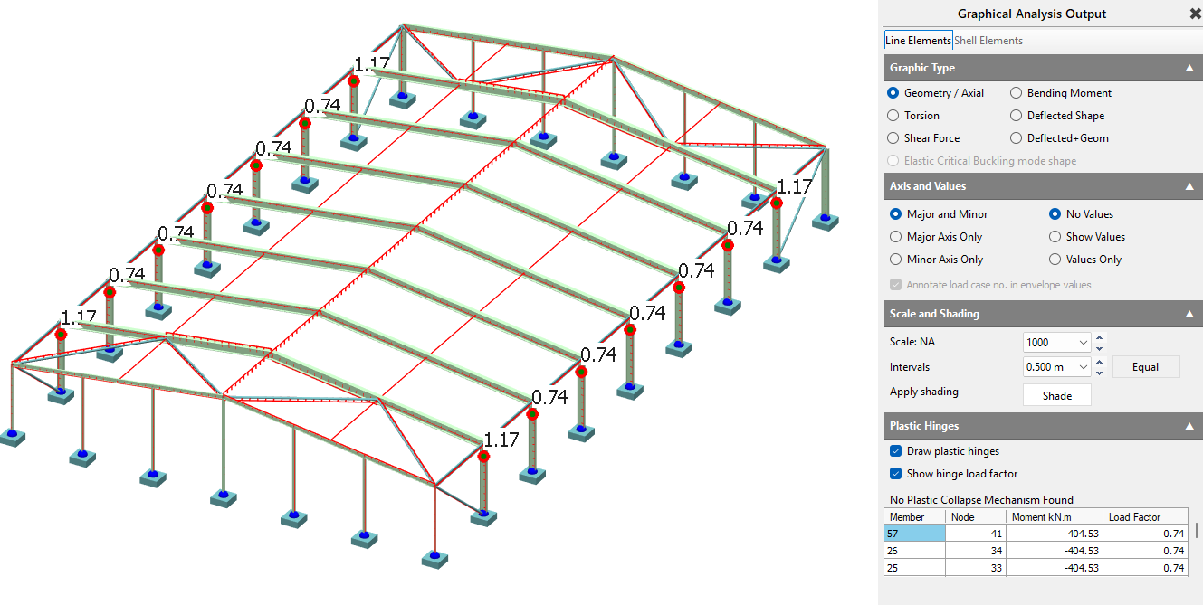
During MasterPort plastic analysis, plastic hinges are permitted to form at the member nodes, where the bending moment is limited to the plastic moment capacity of the section. The procedure begins by analysing the portal frame as normal to calculate member forces and displacements, and then compares the major axis moments to the plastic capacities of the sections. If any moments exceed this capacity, the frame is reanalysed with the residual moments redistributed back into the frame. Once the analysis is complete, MasterPort will notify you of the formation of any plastic hinges and the specific loading cases in which they occurred, or it will confirm if the frame remains fully elastic.
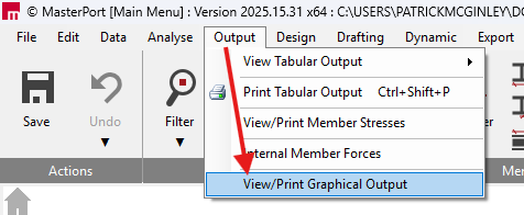
The Plastic Hinge Locations and Load Factors can be seen after the analysis has been carried out, within 'Output > View Graphical Output'.
Auto Sizing of Plastic Members in the Steel Design Module
When utilising the automatic sizing features, the plastic sizing approach specifically attempts to create up to 40% over-stressing below the haunch node in the exterior columns to facilitate the formation of plastic hinges. As a general design rule, plastic hinges should only be allowed to form at higher loads - usually not less than 85% of the ultimate load - to ensure a good balance between column and rafter sizes and to prevent hinges from forming at or near service loading. Furthermore, only one plastic hinge can form in any area limited by two points of contraflexure (such as a pinned support).
Elastic Critical Load Factor (αcr) for Plastic Analysis
Plastic Analysis: For plastic analysis, the stability limit is generally more relaxed. The UK National Annex indicates that for portal frames subject to gravity loads, second-order effects can be neglected if αcr<5, provided the frame meets specific geometric conditions outlined in UK National Annex Clause NA.2.9 . If αcr<5, second-order effects must be accounted for in your plastic design.
Plastic Analysis: True second-order elastic-plastic analysis is highly complex. Instead, MasterPort accounts for second-order effects during plastic design using simple rules based on the Merchant-Rankine reduction method. This method utilizes the elastically derived $\alpha_{cr}$ to calculate a reduction factor, which is then applied to the first-order plastic collapse factor ($\alpha_{p1}$) to determine the second-order elastic-plastic collapse factor ($\alpha_{p2}$).
Understanding plastic hinge behaviour (two common scenarios)
plastic analysis allows hinge formation, which changes stiffness and redistributes moments. That redistribution means:
The hinge sequence matters (it’s not just “check the final bending moment diagram”).
Local hinge formation at the eaves typically increases the ridge sagging moment as loading increases.
A good practical target is that hinges should not form at low load levels; as a rule of thumb, aim for first hinge formation at high load levels (often taken as ≥ ~0.85 of ultimate) to avoid overly-flexible “soft” frames.
Scenario 1 - First hinge forms under the haunch (column side)
Once a hinge forms under the haunch:
.png)
The eaves moment becomes fixed at that value.
The point of contraflexure migrates toward the eaves.
Further load tends to reduce negative moment near the haunch and increase ridge sagging.
A collapse mechanism is reached when additional hinges form near the ridge.
The collapse mechanism is reached when further plastic hinges form near the ridge (in this scenario, plastic hinges cannot form at the upper end of the haunches since the value of the applied moment there is getting smaller with increased load).
If a collapse mechanism is not reached, then it is important to note that increasing the design loads will result in reducing the negative moments over the rafter haunch and increasing the positive moments near the ridge.
Scenario 2 - First hinge forms at the end of the haunch (rafter side)
If the hinge forms at the haunch end:
.png)
The moment there becomes fixed.
With further load, ridge sagging increases and eaves moment behaviour can differ.
Depending on the system, hinge reversal may occur in later stages.
As the values of the column moments and the values of the positive moments near the ridge are increasing simultaneously there are two possibilities:
- The maximum positive moment near the ridge reaches a plastic value and a collapse mechanism is formed;
- The moment under the haunch reaches a plastic value thus forming a new plastic hinge under the haunch. As the load is increased beyond this point, the bending moment diagram along the whole length of the rafter starts to drop and the first plastic hinge that was formed at the end of the haunch disappears (this is known as a plastic hinge reversal). A collapse mechanism will only be reached when further plastic hinges form near the ridge as in the first scenario.
Once more, if a collapse mechanism is not reached, then it is important to note that increasing the design loads will result in reducing the negative moments over the haunch and increasing the positive moments near the ridge.
Practical takeaway: Don’t interpret plastic results solely from a single “final” diagram - check the hinge locations and sequence.
Design philosophy in MasterPort
Portal frame design is typically iterative:
Stage A - Size members
Select rafter/column sizes that satisfy strength and serviceability, based on realistic restraint assumptions.
Stage B - Confirm restraint assumptions
Check that purlin/rail spacing and restraint continuity are adequate to justify the member checks and buckling lengths assumed in Stage A.
In practice, initial sizing is often driven by ULS gravity (dead + imposed) with subsequent checking under the remaining combinations. For multi-bay frames, also review snap-through explicitly.
SCI Guidance References MasterSeries incorporates parameters based on established industry guidance, but it is essential that the designer refers to SCI guidance independently to fully verify compliance:
- For comprehensive rules on frame stability, the limits for using $\alpha_{cr}$, the Merchant-Rankine reduction method, and plastic design, the designer must refer independently to SCI P399 (Design of Steel Portal Frame Buildings to Eurocode 3).
- For the elastic design of single-span portal frames and second-order elastic assessments, please refer independently to SCI P397.
- When considering torsion and warping stiffness in your analysis, the designer must refer independently to SCI P385 (Design of Steel Members with Torsion).
See Also
📄 T02-1 Mono-Pitch Portal Frame
- MasterPort Plus - 3D Multi-Bay Portal Frame Structure Design
📄 T02-3 3D Muilt bay Portal frame
- MasterKey Steel Design Manual
Portal frame “roof spread” and the sway stability case
Portal frames can show artificially low αcr if the check is contaminated by roof spread under gravity. To avoid this, follow the MasterPort approach aligned with SCI portal guidance:
Review αcr using the Sway Stability case that uses notional horizontal loads only, without gravity actions, to isolate true sway behaviour.
Recommended workflow (practical, repeatable)
Model in the Simplified Interface as far as possible
This keeps automatic generation of loads, groups, attributes and bracing/ties consistent.
Run an initial elastic analysis
Check deflections and general load paths.
Review member design groups / briefs
Groups exist to apply one design brief to multiple members. A member can only be in one group.
Auto-size, then auto-restrain
Use Auto Size to select efficient sections by group.
Use Auto Restrain to optimise restraint spacing assumptions.
Re-run analysis and verify plastic behaviour (if using plastic design)
After any significant section changes, re-run analysis; plastic redistribution depends on stiffness.
Check stability (αcr) and enable P-Delta when required
If αcr is below your threshold (commonly 10), enable P-Delta for the governing combinations and design to the second-order results.
Final checks
Confirm restraint assumptions match the real detailing (purlin/rail continuity, restraint positions, base fixity intent).
7. Notes and limitations (scope clarity)
Purlin/rail positions are used for restraint spacing assumptions, but purlins and rails are not designed as secondary members in MasterPort.
Automatic wind generation assumes closed structures; open-sided buildings may require manual wind modelling.
8. See also
Elastic Critical Load Factor / Buckling Analysis in MasterPort
Plastic vs Elastic Analysis with MasterPort
Steel Design Toolbar Overview / Sway Stability / Snap-through / Fire Boundary checks