Member Loading Types
To expand these click on the ‘More Loads’ button.
.png)
Member Load Types
When one of the member load type buttons are pressed, the associated load type is added to the list in the loads editing area. The use of the loads editing area is described above. The purpose and format of each of the load types is described here.
.png)
Standard Member Loads
In the following descriptions the load direction indicator in the load definition is underlined, e.g. in UDLY the Y character defines the load direction. See above for load directions available.
UDLY
Applies a uniformly distributed load W (kN/m) over the full (projected horizontal) length of the member.
D1 UDLY -000.000 ( kN/m )
W (kN/m)
.png)
PY
Applies a point load F in the specified load direction at a distance x measured along the member axis from the lower node number.
D1 PY –000.000 0.000 ( kN,m )
F(kN) x(m)
.png)
PTRY
Applies a partially distributed triangular load starting at a distance x1 with the intensity W1 going to the distance x2 with the intensity W2. All distances are measured from the lower node number.
D1 PTRY –000.000 0.000 0.000 –000.000
W1(kN/m) x1(m) x2(m) W2(kN/m)
.png)
Advanced Member Loads
Density
User can over ride the default value for self-weight. Read more under Member Global Density.
PDLY
Applies a partially distributed load W based on the total load F between the x1 and x2 dimensions measured along the length of the member from the lower node number.
D1 PDLY –000.000 0.000 0.000 (kN,m,m)
F (kN) x1(m) x2(m)
.png)
TY1,2
The total load F is distributed over the full member length in a triangular pattern. The distributed load varies from the maximum intensity W(kN/m) at one end of the member to zero intensity at the other end. For TY1 the W occurs at end 1 of the member, and for TY2 W occurs at end 2 of the member. W = F * 2 /L.
D1 TY1 -000.000 ( kN )
F (kN)
.png)
TYC
The total load F is distributed over the full member length in a triangular pattern. The distributed load varies from zero at one end to the maximum intensity W(kN/m) at the centre of the member, then back to zero at the other end . W = F * 2 /L.
D1 TYC -000.000 ( kN )
F (kN)
.png)
TRY
The total load F is distributed over the full member length in a trapezoidal pattern. The distributed load varies from zero at end 1 to the maximum intensity W(kN/m) at the x1 distance, remaining at that intensity to the x2 distance, then returning to zero at end 2 of the member.
D1 TRY -000.000 0.000 0.000 (kN,m,m)
F (kN) x1(m) x2(m)
.png)
PTY1
The total load F is distributed over a partial length of the member in a triangular pattern. The distributed load varies from the maximum intensity W(kN/m) at a distance of x1(m) along the member to zero intensity at the x2(m) distance end. All distances are measured from the lower node number. W = F * 2 /(x2 - x1).
D1 PTY1 -000.000 0.000 0.000 (kN,m,m)
F (kN) x1(m) x2(m)
PTY2
As per PTY1, however with the zero intensity located at x1 and the maximum intensity W (KN/m) located at the x2. W = F * 2 /(x2 - x1).
D1 PTY1 -000.000 0.000 0.000 (kN,m,m)
F (kN) x1(m) x2(m)
.png)
PMN
Applies a point moment M in the specified load direction at the distance x1 measured long the member axis from the lower node number.
D1 PMN +000.000 0.000 (kN.m,m)
M (kN.m) x1(m)
.png)
EM1,2
Applies the moments M1 and M2 to the local major axis of the member at end 1 and end 2 respectively. Note that no other load directions apply in the load type.
D1 EM1 +000.000 EM2 +000.000 (kN.m)
M1(kN.m) M2(kN.m)
EndM
Applies moments Mz to the major axis and My to the minor axis at the specified end node n (1 or 2) of the member.
D1 EndM 1 +000.000 +000.000 (Mz, My)
n Mz(kN.m) My(kN.m)
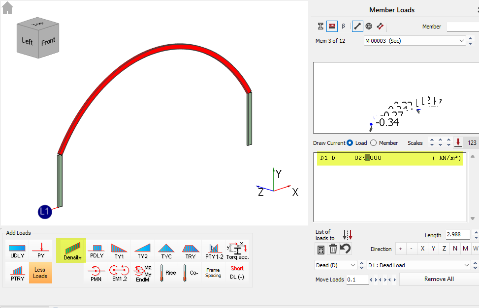
Density
Applies a local density to a member. This option should not to be used in conjunction with the global density option found from the Properties or Loads menus, which automatically applies a single density to all members in the structure.
D1 D 024.000( kN/m3 )
D (kN/m3)
Rise
Defines the temperature differential on a member for the application of thermal loading.
D1 DT +000.000 (Degree C)
Co-
Applies a Co-efficient of thermal expansion to the member. This is more of a material property of the member rather than a load. Thermal loading is not applied to the member until a temperature differential value is applied through the Rise load type. See above.
Like the density a global value of thermal expansion co-efficient can be applied to all member from the Properties menu, in which instance this local member definition should not be used. The value of the co-efficient represents the amount of thermal strain that is produced through a 1 degree Celsius rise in temperature.
D1 Alpha 12.0E-6 (Thermal Expansion)
Short
Applies a shortening of a member along its length. This will result in the strain due to the shortening of the member being taken up in the rest of the frame. Note that the shortening is defined in metres.
D1 DL -00.000 (m)
Torq ecc
The torq ecc. has the effect of offsetting the member loads from the shear centre of the member in both the members local major (ey) and minor axis (ex), hence creating a torque load on the member. The torque eccentricities specified apply to all member loads that follow after it in the list of loads applied to that member. Hence the following example shows how a UDL on a member is made eccentric by 50mm from the minor axis to create a torque force, while the point load remains applied relative to the shear centre of the member.
D1 PY 050.000 01.550 ( kN, m)
UT Torq ex +0.050 ey +0.000 ( m, m )
D1 UDLY 015.000 ( kN/m )
For further information on applying torsional loads and loading on asymmetrical members and their shear centres follow this technical note link - 📄 Defining Torsional Loads
Frame Spacing
The frame spacing has the effect of multiplying all loads that follow after it in the list of loads by the specified factor. The frame spacing value is entered in meter units. For example, when using a frame spacing along with a UDL, the value entered for the UDL can be thought of as the area (kN/m2) load since it will be multiplied by the spacing value.
UT Spacing 01.000 (Multiply AllLoads)
- The 0.25 * Ncr is rearrangement of EN 1993-1-1:2005 eqn 5.8, which is how the same check is presented in EN 1993-1-1:2022.
- Note that in steel design the Ncr values for major and minor axis for this check used the unfactored length (hinged ends) as per EN 1993-1-1:2005 5.3.2 (6).
- The Ncry (major axis) is based on the member length or the Ly manual input in design brief if specified.
- The Ncrz (minor axis) is based on the laterally restrained portion length or the Lz manual input in the design brief if specified.