Understanding Wind Diagonals (Wind Load Reduction Members) in MasterSeries
In MasterFrame, the wind diagonals option is a crucial feature for applying wind load reduction factors, primarily stemming from British Standard (BS 6399 Pt 2) principles, which distinguish between local and global wind effects on a structure.
See also: 📄 Wind Loading – Local Member Wind Diagonal Values
Wind diagonals - now more accurately called Wind Load Reduction Members, are a way for MasterSeries to distinguish between:
Members that experience local wind pressures
(cladding rails, purlins, sheeting lines - subject to high local Cpe suction values)
Members that should only experience overall wind effects
(e.g., vertical bracing, portal frame columns/rafters taking global racking loads)
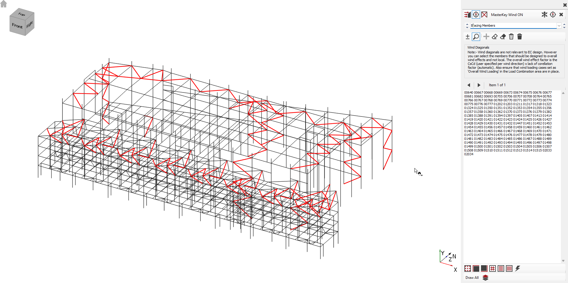
This distinction matters because local Cpe values can be much higher than the overall wind coefficients, and applying them incorrectly would over-design global wind-resisting members (e.g. bracing).
1. Why Wind Load Reduction Members Exist
By default, MasterSeries assumes that all members may receive local wind loads (the more severe ones).
But in a typical building:
The cladding and purlins must resist local pressures
The bracing members, columns, and rafters resist only the global building wind force and should therefore use overall, reduced wind coefficients
So you can place members into Wind Load Reduction Groups, telling the program:
“These members should NOT use the high local Cpe values - only the reduced overall wind loading applies here.”
This avoids artificially inflating design forces.
2. How This Works in Eurocode (EN 1991-1-4)
Under the Eurocode, there is no explicit concept of wind diagonals.
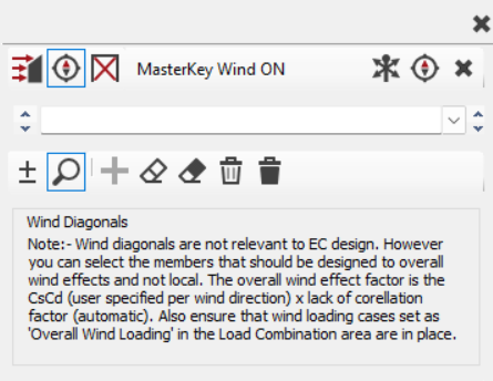
Instead, MasterSeries uses the same principle internally:
Local wind
Uses local Cpe values
Applies to small zones like roof edges, corners, cladding areas
Overall wind
Uses overall Cpe
Then reduces it using:
CsCd (structural size effect and dynamic factor)
Lack-of-correlation factor (wind ward and leeward wind side peak non-simultaneous reduction)
Users control:
The CsCd factors per wind direction
Whether certain members belong to Overall Wind Only groups
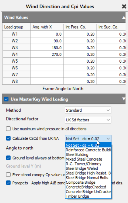
If you set the building type (e.g. Steel Building) in the Wind Directions table, MasterSeries calculates CsCd using UK NA guidance.
3. How This Works in BS 6399 (Historic Method)
Under BS 6399 Part 2, the idea of wind diagonals is explicit, and MasterSeries matches the code closely:

You specify a wind diagonal dimension “a”
(often the average length of bracing bays or elevation diagonals)
The program applies the Wind Size Reduction Factor Ca, reducing loads on:
bracing members
portal frame columns
rafters
If cladding acts as stressed skin, the diagonal dimension a may be taken as the full frame length, providing even larger reduction.
4. Interaction With MasterKey Wind Analysis
When using MasterKey Wind Analysis to generate wind loads:
The program computes dynamic wind pressure qp(z)
Multiplies it by the correct Cpe (local or overall)
Uses the wind diagonal length 'a' (if applicable) to apply the size-reduction rules
Produces reduced overall wind loading for members assigned to the Wind Reduction Groups
You can view:
The wind pressure diagram for each diagonal length a
Which coefficient set (local vs overall) is applied
Graphical wind loading in MasterFrame filtered by diagonal group
This makes it easy to confirm that bracing members are using overall wind effects rather than unintended local suction pressures.
If you'd like, I can also prepare:
Here's a breakdown of the wind diagonals option:
Purpose and Concept
- Size Effect Factor (Ca): Wind diagonals are used to apply a size effect factor (Ca), which influences the wind pressure values. This factor allows for a more efficient design by reducing the applied wind pressure on members that resist wind from the overall frame (globally loaded members) compared to members directly exposed to higher local winds (locally loaded members).
Global vs. Local Loading:
- Globally Loaded Members: These are typically bracing members that carry wind loading from an entire facade of the structure. For these, a larger wind diagonal value, representing the diagonal of the surface area of wind they carry (e.g., 60m for a 56m length), is applied to achieve a reduction in design wind pressure.
- Locally Loaded Members: These include elements like cladding members, or portal frame rafters and columns, which are directly loaded by wind on a smaller, more localised area. By default, these members are assumed to be designed for local wind effects, often with a 5m diagonal (resulting in no size reduction, i.e., Ca=1).
Application Methods
MasterFrame offers flexibility in applying wind diagonals:
- Default Value: All members initially default to a 5m wind diagonal length, which typically results in a more conservative design if no specific diagonals are defined.
- Custom Values for Bracing: Users can define custom wind diagonal values (e.g., 30m or 60m) for specific members, particularly bracing systems, by adding them to Wind Load Reduction groups.
'Applies to local wind on member only' Option:
- This option is specifically useful for members like portal frame rafters or columns where the wind load is applied directly to them.
- When this box is checked, the actual wind member load itself is reduced by the wind diagonal reduction factor.
- A key advantage here is that multiple diagonal load cases are not required for these specific members, simplifying the analysis.
- If this option is not checked, the wind pressure is reduced, but it necessitates multiple load cases for different diagonal values.
- A frame can contain a mixture of wind diagonal groups where this setting is both on and off.
Impact on Loading Cases and Analysis Time
- Defining multiple wind diagonal values (e.g., 30m, 35m, 40m) will significantly increase the number of loading cases that need to be analysed, which can prolong the analysis time.
- To manage this, it is recommended to keep the number of additional diagonal values to a minimum, often a single larger value to cover all globally loaded members, in addition to the 5m default.
- When wind diagonals are used, the software generates different combinations. For instance, wind load cases (designated as 'W' and representing external pressure coefficients only) for the default 5m diagonal are used for individual elements, while only 'W' load combinations (ignoring internal pressure/suction) are generated for longer wind diagonal values (e.g., 30m or 50m) used for overall structural stability and bracing design.
Eurocode vs. British Standard (BS 6399)
- British Standard (BS 6399): The concept of wind diagonals and the Ca factor is explicitly defined in BS 6399 Pt 2 (cl. 2.1.3.4). The "reduction row" in user-defined wind pressures, related to the diagonal distance of the whole structure, is primarily a BS application.
- Eurocode: While MasterFrame uses the BS 6399-2 Directional method for external pressure coefficients in Eurocode design (due to its broader applicability to complex building geometries), the general concern for "wind load reduction on globally loaded values" is less pronounced in Eurocode itself. However, Eurocode wind design still allows for specifying individual members for local or overall wind effects, functioning similarly to wind diagonals in BS. The structural factor CsCd in Eurocode accounts for non-simultaneous peak wind pressures and structural vibrations. This factor contributes to the overall wind effect factor when multiplied by a lack of correlation factor, and it can be entered by the user or automatically determined.
MasterSeries Implementation
MasterSeries allows users to define wind diagonal values early in the wind loading setup. The software can then automatically generate wind loading combinations, which include variations for different wind diagonal values, leading to different dynamic wind pressure (Q) values used in the design.
Load Cases in MasterSeries
The standard W, P and S load cases are generated using the default wind diagonal length (typically 5 m). These cases represent the local wind effects and taking a portal frame as an example, will generally govern the design of:
- purlins,
- rails,
- cladding support members,
- gable posts,
- and other members whose wind effects are primarily influenced by locally applied wind pressures.
These local cases represent situations where the wind effect in a member is governed mainly by the wind load acting directly on that member and its immediate tributary area.
For overall structural stability and bracing design, the user may define additional wind diagonal groups with larger diagonal lengths representing the tributary size of the overall structural wind system (for example 30 m or 50 m). When these groups are defined, the software generates additional W load cases for the larger wind diagonal values.
These additional W cases are intended for the design of globally loaded members such as:
- vertical bracing,
- roof bracing,
- tie systems,
- diaphragm systems,
- and other overall stability elements.
The philosophy behind these overall wind cases is statistical reduction. For larger structural systems, such as portal frames or braced bays, it is unlikely that the peak local wind pressure will occur simultaneously over all wind-loaded surfaces contributing to the member force. The larger wind diagonal length therefore allows an appropriate reduction in the overall wind effect, similar in concept to the Cs factor in Eurocode wind loading.
Internal pressure and suction effects are not considered when assessing overall building stability. As a result:
- additional W cases are generated for the larger wind diagonal values,
- but additional P and S cases are not generated.
Some members, such as portal rafters and portal columns, may fall between purely local and purely global behaviour. Although these members receive locally applied wind loading, the resulting member forces are also influenced by the behaviour of the overall portal frame system. In these situations, the engineer may choose either:
- to leave the members as local wind members,
- or apply a local member wind diagonal reduction using the “Applies to local wind on member only” option.
When using📄 Auto Generate Load Cases (Combinations) , the local/overall wind settings assigned to the load cases should be retained. These settings can also be reviewed or modified individually from the 📄 Load Cases tab.
