Supports (Columns)

The Supports tab is used to define the boundary conditions and supporting structure for a continuous beam. The beams can be analysed either as part of a sub-frame or as a pin-supported continuous beam.
When using the sub-frame option, you enter the column heights above and below the beam, along with the column sizes and end fixity conditions. If you leave a line blank, the software automatically uses the values from the line above. This means that in many cases, a single line of input is enough to define all supports.
You can also define each end span as a cantilever by selecting the relevant check boxes. Upper columns can be removed with a single tick to quickly assess their effect on the analysis. A separate quick-select option is available to set all column heights to the same value.
Span Configuration
First Span as Cantilever
Removes the vertical support at the start of the beam, causing the first span to act as a cantilever. The beam is then supported by the next support in the sequence.
Last Span as Cantilever
Removes the vertical support at the end of the beam so the final span acts as a cantilever. This option is commonly used for balconies or beam extensions.
Support Identification
Support Number
Indicates which support location (for example, Support 1 or Support 2) is currently being edited within a multi-span beam.
Column Geometry and Configuration
Add Upper Columns
Includes columns above the beam level in the analysis. If this option is not selected, the software assumes there is no structure above the beam at that support.
Height of Lower Column
Sets the vertical height of the column below the beam. A value of zero removes the physical column while keeping the support node.
Height of Upper Column
Sets the vertical height of the column above the beam. This value is used to calculate stiffness and the moments transferred into the beam from the structure above.
Column Breadth
The column dimension parallel to the beam.
Column Depth
The column dimension perpendicular to the beam.
Make All Column Heights Equal
Automatically applies the current column height to all supports in the beam, helping ensure consistency and reducing input time.
Fixity and Restraints
Fixity of Bottom of Column
Defines the support condition at the base of the lower column. Options typically include pinned, fixed, or partial fixity.
Fixity of Top of Column
Defines the support condition at the top of the upper column, controlling how the beam interacts with the structure above.
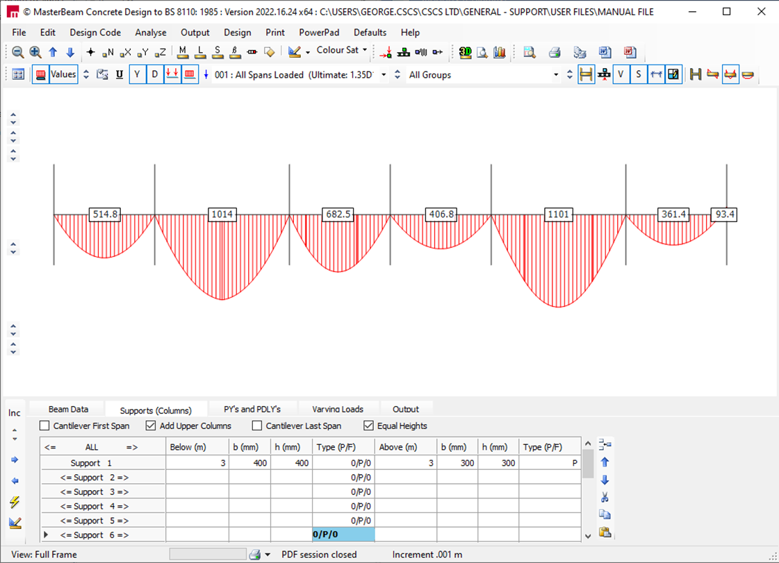
In the Type (P/F) column, you can enter the percentage fixity for the beam ends on either side of the column.
For example, entering 0 / P / 0 specifies a pinned connection at the base of the column and 0% fixity for the beams on both sides. This results in pinned beam ends and creates a series of simply supported beams, as shown below.

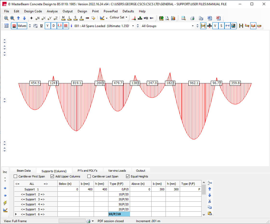
Percentage fixities can also be applied to the ends of the beam spans,
if required, as shown below.

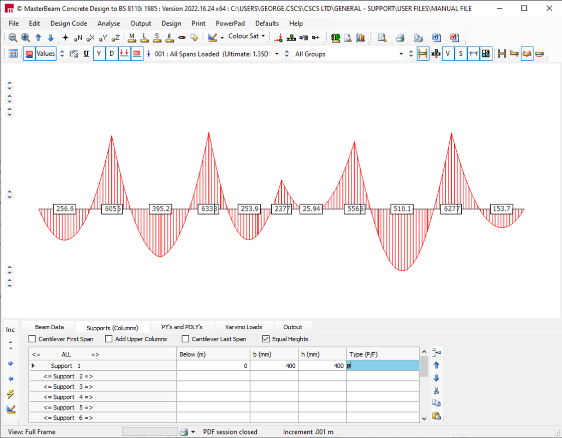
To analyse as a continuous beam, the column
heights should be set to zero, and the support
types to pinned, giving the result below. Where
there are no columns the support
definition is then at the beam level.

As you change any input data, the calculations and force and moment diagrams update instantly. This allows you to see the effect of each change immediately.
Advanced feature: Clicking the arrow buttons at either end of a Support Number button moves the column in 0.1 m increments while keeping the total span length unchanged. This makes it easy to quickly assess the impact of moving a support along the beam.
This feature is particularly useful for continuous ground beams supported on piles, where pile positions may need to be adjusted to optimise pile capacity.
Old Manual Entry
The beams can be analysed
as part of a sub-frame or as a pin supported continuous beam. As a sub-frame the column heights above and below are specified
along with the column dimensions and end fixities.
If no data is entered into a
line, it will assume the data from the line above, thus a single line entry can be sufficient to define all the supports. Each end span can be defined as a cantilever if required, using
the check boxes.
The upper columns can be omitted,
with the tick of one box, to see what effect this may have. There
is also the quick tick option to make all column heights the same.
In the left Type(P/F) column, the percentage fixity of the ends of the beams to either side of the column can be entered. For example, entering 0/P/0 will give a pinned connection to the base of the column and 0% fixity to the beams connected to both sides of this column, thus pinning the beam ends, creating a series of simply supported beams, as shown below.
Percentage fixities can also be applied to the ends of the beam spans,
if required, as shown below.
To analyse as a continuous beam, the column
heights should be set to zero, and the support
types to pinned, giving the result below. Where
there are no columns the support
definition is then at the beam level.
As data is altered, the calculations and forces/moments diagrams
are changed immediately, so the effect
of any changes can be seen
right away.
Advanced feature:- Clicking on the arrow at either end of a Support Number button will move the column by 0.1m at a time, with the total cumulative span lengths staying constant. Thus the effect of moving a support under a beam can be quickly assessed. This could be useful, for instance, where a continuous ground beam is supported on piles, and the pile positions need to be optimised to suit the maximum pile capacity. (Note:- the increment value of 0.1m mentioned above can be altered in the top left corner of the tabs area under 'Inc'.)
See Also