Beam Designers - Defining Support Conditions
https://files.masterseries.com/documents/Beams-bd_pins.pdf
The pinning of all members is controlled by the switches on the columns as follows.
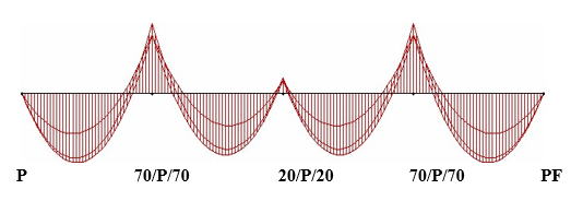
For the Lower Column the full description of 20/P/30 for the type means
Examples
|
|
Left Beam |
Column Base |
Right Beam |
|
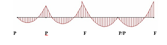
P |
Fixed |
Pinned |
Fixed |
|
0/F/0 |
Pinned |
Fixed |
Pinned |
|
0/P/0 (see notes) |
Pinned |
Pinned |
Pinned |
|
20/F/30 |
20% fixity |
Fixed |
30% fixity |
|
100/P/100 = P |
Fixed |
Pinned |
Fixed |
|
20 |
20% fixity |
As previous base |
20% fixity |
Notes:
1. 0/P/0 should not be used on all supports as it may give an unstable structure with weird results. As this is in essence a Beam designer and 0/F/0 will give you the same result but with stability.
2. Moment redistribution is best performed inside the concrete design module as this gives greater control.
Examples
|
For |
Input |
|
|
P |
|
|
0/F/0 |


Upper Columns
The upper Column, if present, only has P for pinned and F for fixed at the remote end.
Knife-Edge Beams
Special conditions for knife-edge beams i.e. no columns