Lateral Torsional Buckling (LTB) Inputs
Lateral Torsional Buckling (LTB) occurs when a beam bends about its major axis and the compression flange is not restrained, causing the member to twist sideways under bending. The inputs in this section let you define restraint conditions, effective lengths, and modification factors so the design checks match your real structure.
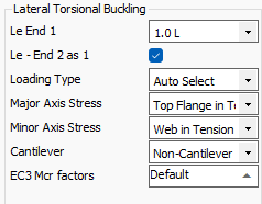
Effective length (Le, K-factors):
Defines the unbraced length for LTB
- Le End 1: Effective length factor for the start (lower node-numbered) end of the beam.
With the fully restrained option set, this will be reflected in the calculation outputs, and the lateral restraint input will have no effect on the design.
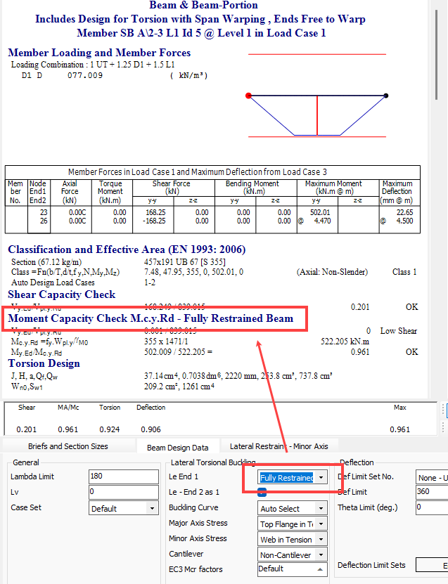
Where the beam is not fully restrained for LTB, then the restraint positions are defined in the 📄 Lateral Restraints Tab
Le End 2 as 1: Check this box to use the same effective length at end 2 (higher node-numbered).
If un-checked the additional Le End 2 input is presented and the software will average the two factors.
Loading Type
- Control over shape of BM used for; C1,2,3 factor calculation and Table B.3 in EC design; Table 18 m_LT in BS 5950:2000 design
- Pre MasterSeries 2025

- MasterSeries 2025+

- Pre MasterSeries 2025
If set to Autoselect, MasterSeries automatically picks the curve appropriate to the member type and loading.
Major Axis Stress
The new inputs in MasterSeries 2024 allow you to explicitly tell the software which part of the section is in compression (or tension) from the major axis moment, affecting section classification and lateral torsional buckling checks.
Unequal Angles:
- Long Leg in Compression:
- Short Leg in Compression:
In BS 5950:2000 design, controls the sign of the monosymmetric index value B.9.3 used in the calculation of the buckling slenderness faction 'v'.
Symmetrical I sections:
- Top Flange in Tension:
- Top Flange in Compression:
In MasterSeries 2024 and below, this setting used to control the Zj value used in Mcr and section classification of asymmetrical I sections. In MasterSeries 2025 for asymmetrical I section that have moment this input is not enabled as the flange that is in compression is automatically controlled by the sign of moment. When double curvature bending is detected both flanges are seem to be in compression, and the most critical section classification is chosen. In addition both compression flange side buckling checks are performed, with the most critical chosen.
T sections:
- Flange in Tension:
- Flange in Compression:
In BS 5950:2000 design, controls the sign of the monosymmetric index value B.2.8 used in the calculation of the buckling slenderness faction 'v'. This method of calculating the dimensionless slenderness ratio for lateral torsional buckling λ_LT used also used in Eurocode design.
Other Sections:
- Top in Tension:
- Top in Compression:
More generally, this setting also influences the additional flange plate projection classification (on I sections, Channel Sections and RHS/RHS hollow sections) by dictating if the plate is in compression or tension from the major axis moment.
Minor Axis Stress
This is used for Channel and PFC shaped sections to dictate sense of force created in the web from minor-axis bending moment.
Web in Tension:
Web in Compression:
Influences the Minor axis Plastic Moment Capacity values in the presence of axial loading. Influences section classification by dictating sense of force created in the web from minor axis moment, however member axial force is also used to calculate value of compression stress in the web.
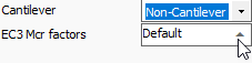
Cantilever / Non-Cantilever:
Captures Warping Condition at supports
MasterSeries tests the geometry to see if the beam qualifies as a cantilever. The dropdown will update automatically, but can be adjusted manually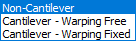
Non-Cantilever
BS5950:2000 General Case for beams Table 18
EC3: Equivalent Uniform Moment factor C1 default values can be overwritten in the EC3 Mcr Factors below
Cantilever - Warping Free: End allows twist without restraint. This is common at free ends.

BS5950:2000 For cantilevers without intermediate lateral restraint: mLT = 1.00
EC3: Equivalent Uniform Moment factor C1 taken from NCCI SN006
- Cantilever - Warping Fixed: End prevents twist, e.g. by stiffeners, deep connections, or diaphragm action.

- BS5950:2000 For cantilevers without intermediate lateral restraint: mLT = 1.00
- EC3: Equivalent Uniform Moment factor C1 taken from NCCI SN006
Eurocode factors (C1–C3):
EC3 Only - Refine Mcr calculations to reflect bending diagram and load application

- Eurocode modification factors used in the elastic critical moment equation.
- Depend on the shape of the bending moment diagram.
- Value is automatically determined by the software.
zg Factor
- Height of load application above the beam’s shear centre (in mm).
Positive value = load applied above shear centre (destabilising).
Default = 0 (assumes load passes through shear centre).