Beam and Beam-Portion Design Brief
The Beam and Beam Portion design brief is aimed at the design of beams. This brief will ignore any axial load on the member, whether there is axial tension or compression. As such, the beam and beam-portion design brief is not suitable for columns, or for members where the axial force is not negligible.
The Beam and Beam-Portion design brief is applicable for members with single axis bending moment. The Beam and Beam-Portion brief will check for local moment capacity, lateral torsional stability, shear capacity, deflection criteria and slenderness ratio. The user controlled inputs include specifying the restraint condition and, where appropriate, restraint positions to the minor axis (for lateral torsional buckling). Additional user inputs include specifying user determined C1-C3 factors (in the Eurocode design) and the vertical distance from the shear centre of the beam to the point of application of the load, to account for destabilising loads. There is also the option to consider the design of the section in torsion.
The Beam and Beam-Portion design brief ignores any axial forces in the member. It also ignores any minor axis bending. Both of these items are noted in the the design brief title at the top of the design output screen. The Member Forces and Maximum Deflection summary table will note the member forces, including axial force and major and minor axes bending. It is the responsibility of the design engineer to ensure that the correct design brief is applied to any particular member.
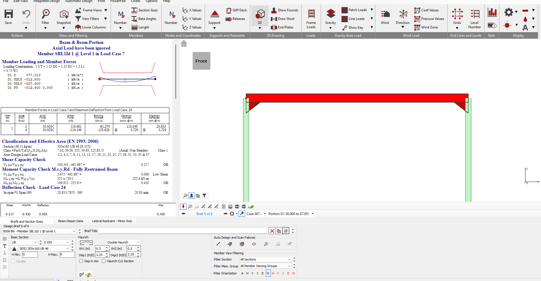
Once a Beam and Beam-Portion design brief is applied to a member, the basic screen layout is as follows.
Briefs and Section Sizes
The Briefs and Section Sizes tab contains options to amend the steel member section size, to make the member a compound member (which also provides options to provide plates to the member) and to add web openings. Within the Briefs and Section Sizes, there are also options to carry out an autodesign on the selected member or on all members visible on screen.
For more detailed information on the AutoDesign area, see the Designing a Member section.
The 'Options(menu)> Change Current Beam Brief to A+M' allows the design brief to be quickly changed to an Axial with Moment design brief. That would be used in cases where, for example, the member has axial force (which is ignored in the Beam and Beam-Portion brief) and the brief needs to be changed, but saves the need to delete the Beam and Beam-Portion brief before changing.
Beam Design Data
The layout of the Beam Design Data tab is shown below.
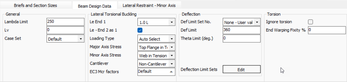
- Lambda limit - Slenderness limit. This was originally a BS 5950 check, but was dropped in later version of the code and does not appear in the Eurocodes. However, it was opted to maintain this input in the steel design.
- Lv - the distance between connection locations in a double member. The input is specified in metres (m). If a value of zero is used, the software will default to using the actual member length.
- Case Set-This allows users to define a load set that can be applied to selected members. This is useful for performing additional or localized checks on specific structural elements . Refer 📄 DRAFT Design/Deflection Load Case Sets (2024) .
- Buckling Curve - This option allows the user to control the tables used to determine LTB factors ( determined using the British Standard method). Setting this drop down to 'Auto select' means the software will automatically pick the appropriate table from BS 5950-1.
- Le End 1 & Le End 2- The effective lengths of the beam are for use in the lateral torsional buckling check . Entering values for Le end 1 & Le end 2 allows different end conditions to be considered. Where different end conditions exist the software will use the average of the two . To set the end of the beam to be the same as the start, check "As End1".
- EC3 Mcr Factors - Eurocode factors for modifying the elastic critical buckling moment Mcr equation. The C factors are dependant on the shape of the bending moment diagram of the beam or part of the beam under consideration. This can be left default , where The software will automatically determine the factors or C1,C2,C3 values van be manually entered. The zg input only needs to be used for destabilising or stabilising loads. With a default value of zg = 0 the software takes the load to be applied at the shear centre of the member. Values only need to be input in the design brief if the user wishes to overwrite the values.
- Theta Limit - this is the rotation limit for use in designs where torsion is present. IF the "Ignore Torsion" option is set, the Theta limit is not active and the value input is not relevant. When the design is set to include the torsion, the Theta Limit defaults to a value of 2 degrees. This is the SCI recommended limit.
- Spacing - for use with double members. The spacing defines the gap between double members. The input value is in millimetres (mm). The default setting is zero.
- FL/UL - the ratio between the factored loads (FL) and unfactored loads (UL). This is used in the British Standard design as part of the check to ensure that Mc = Py*S <= 1.2 py. This check is not used in the EC design so the FL/UL factor is not required.
- Def Limit - The Span/Deflection limit used for the serviceability deflection check. The default value is 360. The deflection is checked for the worst case serviceability load case. Clicking on the input box will show a small icon at the right of the input. Using the mouse and clicking on this icon will bring up the Deflection Limits table. In this table, up to 30 user defined deflection limits can be specified. With a user specified set of limits added to the table, these new deflection limits can be used by inputting the line number of the table into the Def Limit input in place of a span/deflection limit.
.png)
For further information on the nodal and member and in-span deflections see📄 Member and Nodal Deflections in MasterFrame analysis results and steel design
Non doubly symmetric members
For members which are not doubly symmetric, for example, angles or channel sections, setting whether the flange is in tension or compression, or whether the web is in tension or compression are set using the drop downs below the LTB settings. If the section selected is an angle, the drop down contents will modify to Long Leg in Compression or Tension and WEB in Compression or Tension.
Torsion Design
For members with torsional loading, torsion can be considered in the design using the torsional inputs. These are located at the right of the Beam and Beam-portion tab. The torsion inputs are shown below.

The default setting is that the torsion design checks are off. To consider Torsion, the top drop down needs to be changed from "Ignore Torsion". The drop down allows the setting of the degree of restraint to warping at the member ends. It should be noted that obtaining restraint to warping is often not practical or possible. For further details, reference should be made to a relevant design guide or SCI publication.
To display a diagram related to the torsion design, use the bottom drop down.
If you wish to turn off the torsion design for the whole model, check the 'Options (menu)> Check Torsion Global On/Off' option.
Therefore, the values in the steel design are more accurate where torsional rotation is concerned than those derived directly from the initial frame analysis.
Lateral Restraints-Minor Axis
The lateral restraints tab provides inputs which control the restraints to the member for use in the lateral torsional bending design checks. The lateral restraints only restrain the minor axis in bending.
The layout of the Lateral Restraint tab in the Beam and Beam Portion design brief is shown below.
The position of lateral restraints can be defined on any member using the Portion inputs. The "Start at X - End 1" input controls the distance to the first lateral restraint with the start distance being defined from the start of the member. The start of any member is defined as the end with the lowest numbered node. The position of the restraints are then defined by the length between restraints as defined by the Equal spacing and Portion Length End1/2 inputs.
The "Equal Spacing (m)" and "No. Of Equals Spaces" provides portions throughout the member. Where "No. Of Equal Spaces" is zero then equal spaces will fill the length of the member.
Variable portion length can also be entered for 1 and end 2. Variable Portion Lengths - End 1 are measured from end 1 of the member or the Start at X value if defined.
Where a member has other members framing into it, for example, a primary beam supporting secondary beams, the portions can be created automatically at the position of the connecting members. This can be done by either clicking on the "Generate Rest. at Joining mems", or, alternatively, by checking the "Auto Restrain at incoming" checkbox as shown in the image.
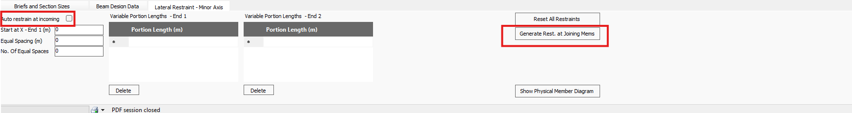 The Generate Restraint at Joining Mems option will automatically input the Portion lengths in the End 1 grid. This means that the position of the restraints can be amended manually. When the "Auto Restrain at incoming" check box is selected, the Portion input and the Generate Restraint at Joining Members options are disabled. Any amendments to the position of the incoming members in the Masterframe model will then be automatically accounted for in the design brief on the amended members.
A typical layout of the Lateral Restraints on a primary beam is shown below.
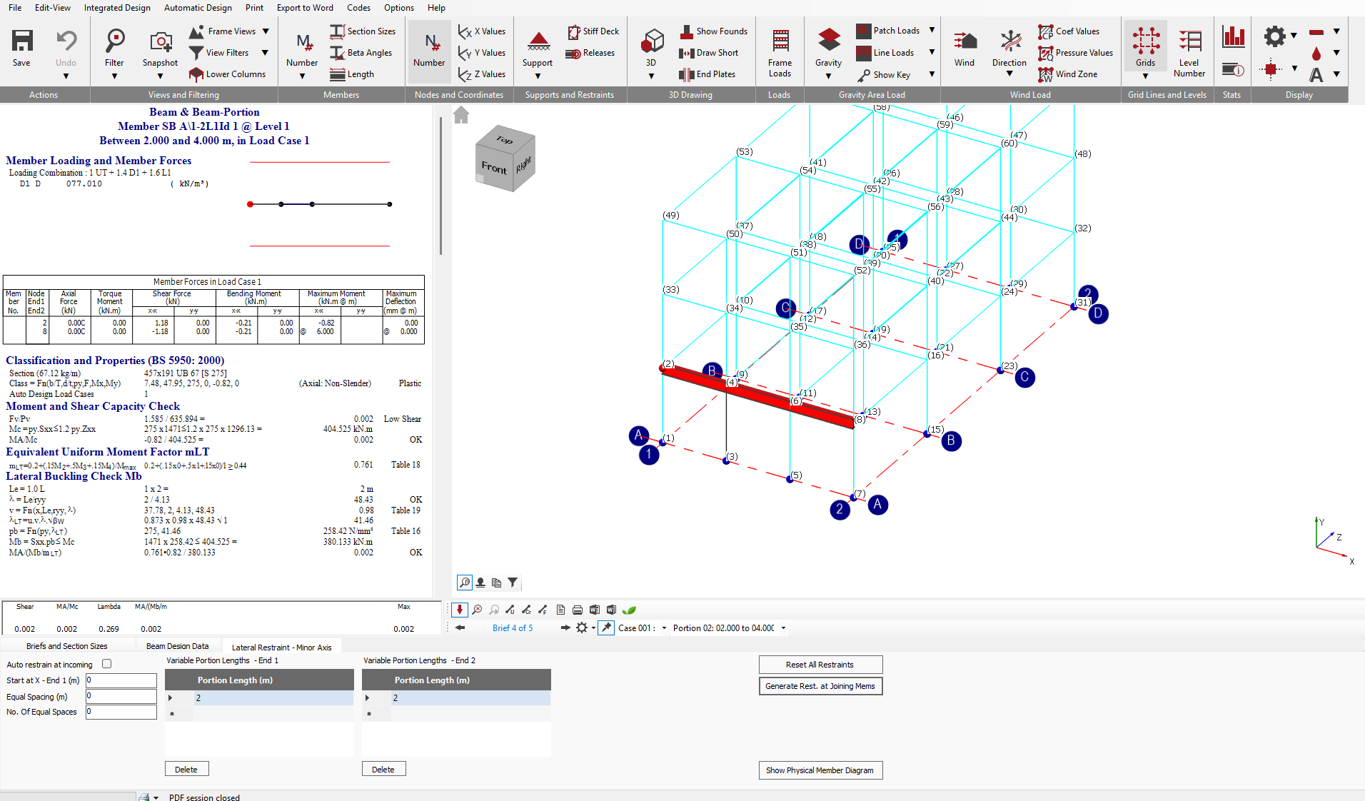
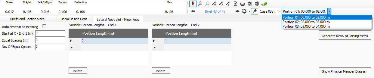
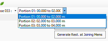
The position of the portions are indicated in the results diagram at the top of the results area. To view the design results for any particular portion, the portion can be selected either graphically, by using the mouse to click on the portion in the results diagram at the top of the design output area. The active portion by highlighted in blue in the results diagram. The current selected portion is also noted in the Portion drop down. The current portion is displayed as .png) . The Portion drop down also provides an alternative method for selecting the portion to check, by expanding the drop down. The drop down notes the Portion number along with the position of the portion with the distances noted from the start of the member. For the above member, the expanded drop down appears as shown below.
. The Portion drop down also provides an alternative method for selecting the portion to check, by expanding the drop down. The drop down notes the Portion number along with the position of the portion with the distances noted from the start of the member. For the above member, the expanded drop down appears as shown below.
The selected portion is indicated with a blue highlight in the graphics. The relevant portion input also highlights.