Member and Nodal Deflections in MasterFrame analysis results and steel design
Date: 17/03/2022
Versions: 2021.15 +
Program: MasterFrame Analysis, MasterKey Steel Design
Member and Nodal Deflections in MasterFrame analysis results and steel design
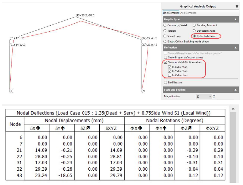
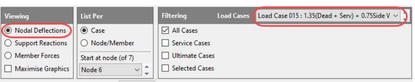
Nodal Deflections The nodal deflections after analysis are the displacements of the nodes from their original positions prior to any loading being applied. As loading is applied the frame will deflect and the nodes will move. These nodal deflections can be displayed in the output graphics and in tabular format as shown below.
Member Deflections
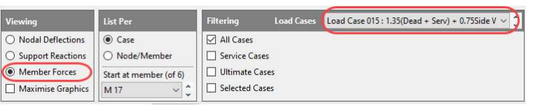
The member deflection after analysis is the displacement of a member from a straight line connecting its displaced end nodes. This is called the in-span deflection. Note that it is not the deflection of the member from its original position in the frame, but from the displaced end nodes. This is the deflection that would usually be checked against span/360 or a similar limitation so as to limit damage to the local brittle finishes.
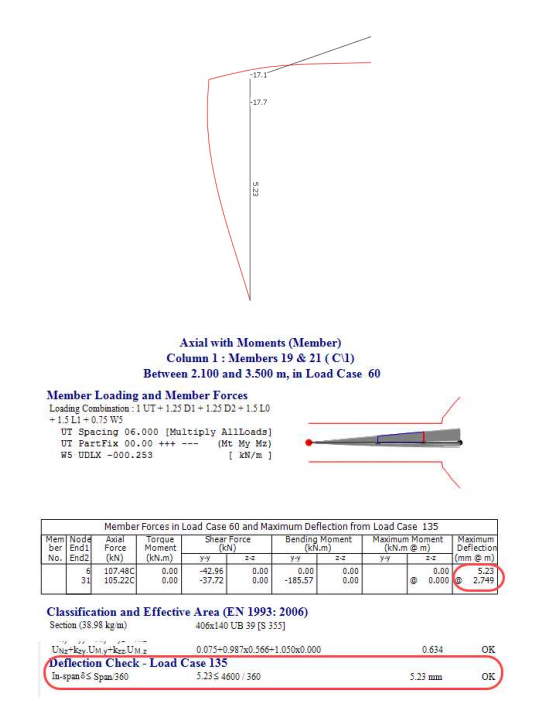
Examples – portal frame and multi-storey building
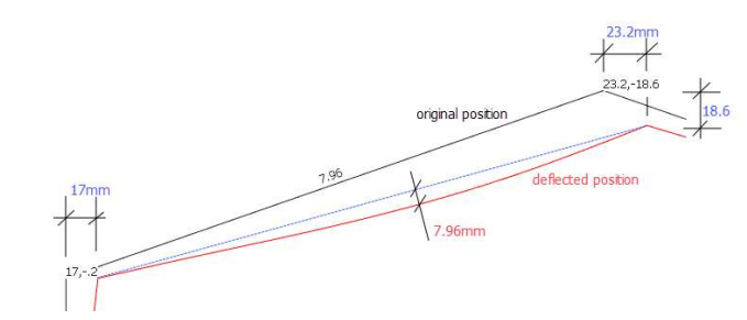
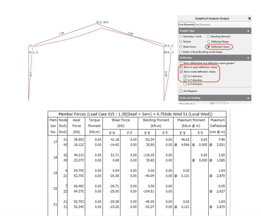
Diagram showing nodal displacements and in-member deflection of a portal rafter
The portal frame has moved sideways and downwards under dead and live and side wind loading. The ends of the rafter have displaced by the amounts shown in blue. However, the rafter itself has only deflected 7.96mm from a straight line connecting its two ends. Similarly for the portal leg below where the column has deflected 5.23mm due to bending curvature.
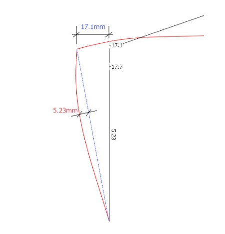
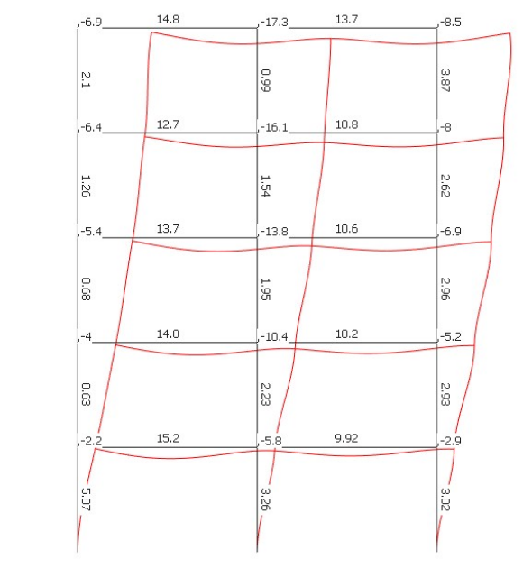
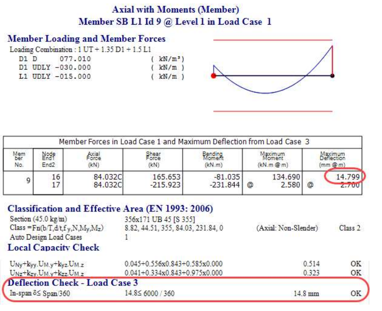
Diagram showing nodal displacements and in-member deflections in a multi-storey frame
For the top left beam in this multi-storey model, the end nodes are deflecting vertically by 6.9mm and 17.3mm. The in-span deflection is shown as 14.8mm.
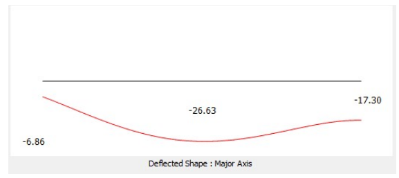
When you look at the Member Diagram for this beam it shows both end displacements and the overall beam deflection from its original position. This max value will be at approx the middle of the beam and is made up of the average of the end node displacements plus the in-span deflection.
(6.9 + 17.3)/2 + 14.8 = 26.9mm approx (Note that the max deflection may not necessarily be at the exact centre of the beam).
Steel Design
In the steel design of a member the deflection check uses the in-span deflection of the member due to its bending as this is what you want to check for against the finishes deflection criteria.
So, in the example above, the top beam is checked for 14.8mm against span/360.
Similarly for a portal column leg, the steel design deflection check is for the deflection of the member due to its bending curvature as opposed to the max displacement of the node at its top, in this case 5.23mm in-span deflection and not the 17.1mm at its head.
Any nodal displacement criteria should be checked separately for the frame, eg, apex deflection or eaves horizontal movement for a portal frame.
Regards,
MasterSeries Team