Grid Lines
See – MasterFrame Space Frame > Creating a Model > Grid Lines > 📄 Grid Lines for full explanation.
Floor Plan
Initially a plan view of a floor plan appears on screen along with a side panel where the floor layout can be defined.
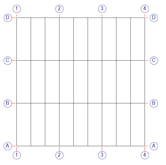
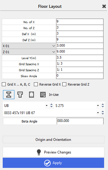
It starts with 9 bays in the X direction and 3 bays in the Z direction, with the X spacing defined as 3m and the Z spacing as 9m. If you drop the down arrow next to the X 01 line you will display all the X bay spacings, which can then be altered where required so that all spacings can vary in the X direction. The same can be achieved for the Z spacings.
The Y level for the floor can be defined. This initially starts off at 3.5m so that columns can be later added below this first floor level.
The Grid Spacing X and Z allow you to space the gridlines in both the X and Z axes. For example, the X gridlines are spaced at 1;3 meaning the first grid will start at line 1 and the next grid a further 3 lines across, as shown above. In the Z direction the gridlines are spaced at 1;1 meaning the first grid starts at line 1 and the next one line along and so on.
The gridlines can be skewed in one direction using the skew angle option. You can also select the box to allow the X grids to change from numbered to lettered – Grid X .. A,B,C. The direction of the lettering or numbering can also be reversed for both X and Z grids.
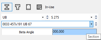
You can select the type and size of basic section that you want to start the frame off with. These can be steel, T-shaped concrete, rectangular concrete or rectangular timber. The orientation (beta angle) of the members can be defined. They will normally sit at 0 degrees, major axis vertical.
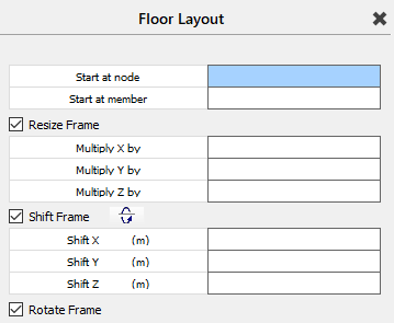
Origin and orientation
By clicking on the Origin and Orientation button you can manipulate the position of the frame. This isn’t usually necessary when initially starting a frame but can be used later to resize, shift or rotate the frame or when importing another frame into the existing frame – see ‘Modifying Geometry - Change Coordinate Tools’ and ‘Creating a Model – Add Frame – Import a Frame’ in the main MasterFrame manual for details on how to use these options.
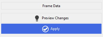
Preview & Apply
The Frame Data button will take you out of the Origin and Orientation option, back to the original input panel. You can always Preview the changes before Applying them if you are happy with these changes.
Snap Grid
See ‘MasterFrame – Creating a Model – Add Members (General)’ in manual for explanation of right hand 📄 Add Members (General) panel.
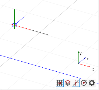
In the bottom right of the graphics area there are several icons which relate to the snap grid. These are:-
 Snap grid – on/off
 Show CAD Layer – your view must be on the CAD Layer plane
 Object Snaps – on/off – right click for quick settings
 Polar Snaps – on/off – set the polar angles in settings
 Snap settings – snap grid, object snaps and tracking
Snap Grid Settings
For further details see 📄 Add Members (General)
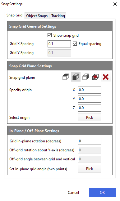
Snap Grid General Settings
The first tick box allows you to switch on/off the snap grid. The grid spacings can be set in metres. If equal spacing is ticked then the snap grid will be square, otherwise you can set different spacings in the 2 directions. Also see Snap Grid Spacing.
Snap Grid Plane Settings
You can select which snap grid plane you wish to display – XZ, XY or YZ planes. The fourth option allows you to set a plane that is not in any of the 3 orthogonal planes by specifying angles in the options below. The red X button sets the snap grid origin back to 0, 0, 0. Alternatively you can specify an origin using X, Y and Z coordinates or pick an origin position off the existing frame.
In-Plane/Off-Plane Settings
When any of the Snap Grid Plane axes are chosen, you can offset the grid from the chosen plane using the Grid in-plane rotation (degrees) option, eg, 45 degrees will rotate the plane from the original plane position through 45 degrees.
When the 4th button along in the Snap Grid Plane Settings is in use, the grid can be offset from the 3 orthogonal axes using the off-grid rotation (rotates the grid about the Y axis) and off-grid angle (set angle between grid and vertical) options.
The bottom option to Set in-plane grid angle (two points) allows you to graphically pick 2 points to set the snap grid angle and/or plane.
Also see Snap Grid Orientation.
Object Snaps Settings
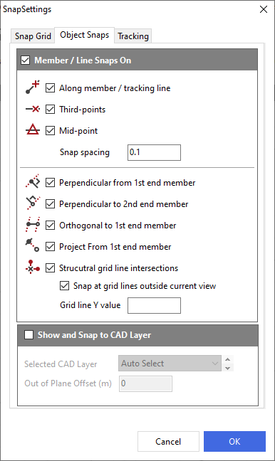
Member / Line Snaps On
The Object Snaps settings dictate to the program which snaps are on or off when using functions such as Add Column or Add Member. Most of these are fairly self-explanatory.
You can snap to a point along a member or on a tracking line projecting from the member along its length. You can snap to third or mid points along a member and set a snap spacing default dimension.
You can also set new members perpendicular to existing members or orthogonal to them or have them snapping to grid line intersections.
Show and Snap to CAD Layer
If CAD Layers have already been added to the model, you can select which layer to make active.
Also see Snap Points
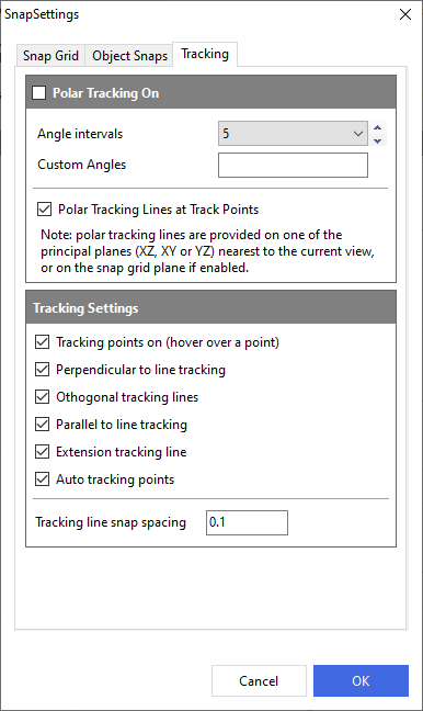
Tracking Settings
Also see Tracking Lines and Points - 2nd end of member and
Tracking Lines and Points - 1st end of member Below
📄 Creating a MasterFrame file
Polar Tracking On
Polar tracking can be used to position end nodes of members. There are a set of common angles or you can set your own custom angles where required. Polar tracking lines can also be used. These usually adhere to the nearest principal plane.
Also see Polar Tracking
Tracking Settings
A number of additional tracking possibilities can be switched on to aid placement of members.
Also see Parallel Tracking and Top Level Nodes