Pad Foundations Editing Tabs
The MasterKey Concrete Pad Foundation module requires a column (or vertical member) to be modelled in MasterFrame in order to generate and design a pad foundation. The integration depends on there being a structural member at the support so the software can recognise and define the foundation location.
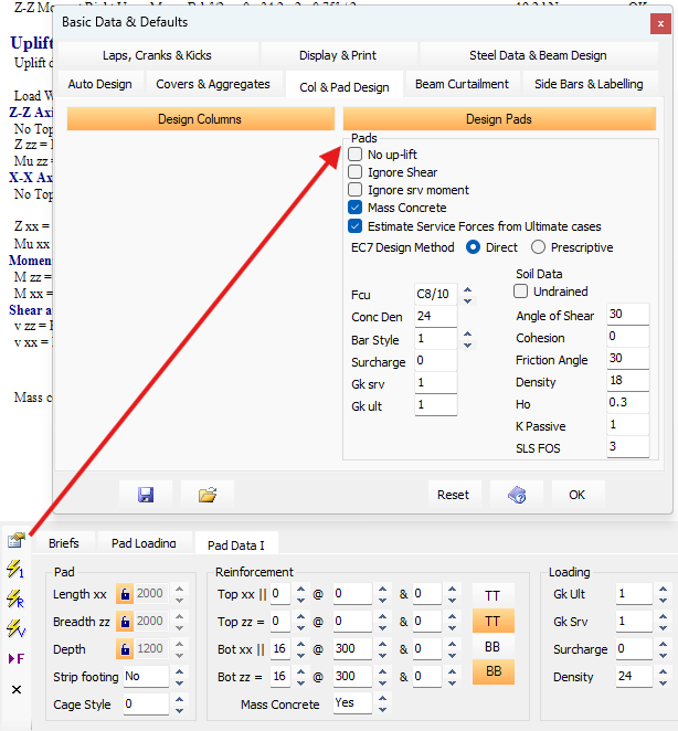
Edit Global Basic Data and Design Defaults
Users can amend the Basic Data & Defaults from within the Pad Design module.
For information on each of the options within the module, refer to 📄 Concrete Pads Basic Data
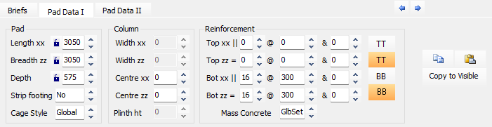
Pad Data I
Length xx
The basic physical dimension of the foundation along the X-axis.
Breadth zz
The basic physical dimension of the foundation along the Z-axis.
Depth
The total thickness of the concrete pad foundation. These three dimensions can be manually locked to prevent them from being changed during an AutoDesign.
Strip Footing
A setting to specify whether the foundation is a standard pad or a strip footing; if a strip footing is selected, the dimension in the direction of the wall is typically set to 1000 mm.
Cage Style
Defines the detailing style for the reinforcement cage, with options including Straight-Bars, Bobbed-Bars, or Full-height U-Bars.
Column Section
Width xx and Width zz:
The dimensions of the column interface, which can be manually entered to account for concrete casing or a plinth. If these fields are left as zero, the software defaults to the column size defined in the MasterFrame analytical model.
Centre xx and Centre zz
The distance from the edge of the foundation to the center of the column for the respective axes. If left at zero, the column is automatically centered on the pad.
Plinth ht (Plinth Height)
The height of a plinth or dwarf column that was not included in the original frame analysis. Any horizontal shear forces are multiplied by this height to calculate a resultant additional moment at the base of the foundation.
Reinforcement Section
Top xx and Top zz
These fields allow you to specify the diameter and spacing (pitch) for reinforcement bars located in the top face of the pad foundation in each orthogonal direction.
Bot xx and Bot zz
Similar to the top steel, these fields define the diameter and spacing for the bottom reinforcement bars in the XX and ZZ directions.
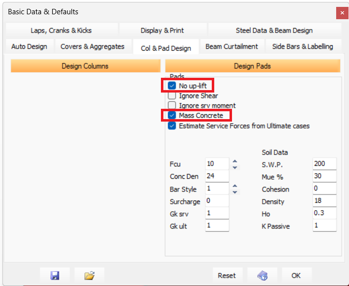
Mass Concrete
A checkbox (or dropdown) used to design the pad as unreinforced mass concrete. When set to 'Global' the design, in relation to mass concrete, will proceed as per global settings. When set to 'Yes' or 'No' the design will proceed directly based on this input and will ignore the global setting in relation to mass concrete design. When mass concrete design is active, the foundation is designed with no reinforcement bars, relying solely on the concrete's tensile strength and the pad's depth-to-projection ratios to resist bending and shear.
When checked, the 'No up-lift' checkbox (found within the Global Settings), the software will size the pad such that the resultant force from moment and axial lies within the middle third of the pad.
When left unchecked the software will size the pad such that a tolerable amount of uplift may be permitted.
- If the pad is reinforced then this may result in top reinforcing bars being added to the pad,
- if the pad is unreinforced (mass concrete), bending stresses resulting form any permitted uplift will be kept within the pad's concrete tensile limits.
Pad Data II: Loading
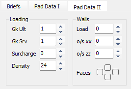
Gk Ult
Partial safety factor on the Density and Surcharge in ultimate load cases. Defaults to Global value.
Gk Srv
Partial safety factor on the Density and Surcharge in service load cases. Defaults to Global value.
Surcharge
Surcharge to top of base kN/m2 applied to whole base. Defaults to Global value.
Density
Density of the concrete in kN/m3. Defaults to Global value.
SWP
Safe Working Pressure kN/m2 or the Un-Factored (Service) Bearing pressure used in sizing the pad. The program identifies a loading case as service case if all load factors are equal or less than 1.00. Defaults to Global value.
Pad Data II: Walls
Load
Service/working load (kN/m) per meter run.
o/s xx
Wall offset parallel to the XX axis (mm). Defaults to centreline of pad.
o/s zz
Wall offset parallel to the ZZ axis (mm). Defaults to centreline of pad.
Faces
| Define which faces of the foundation the wall exists on. See example opposite If NO wall projections (faces) are defined then the load is assumed to be total intensity (kN). Note - All wall loads are resolved back to the column as a point load and induced moments. .png) |
.png)