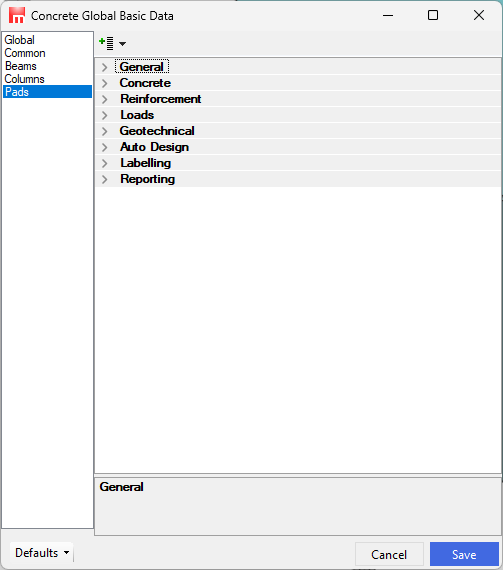
Concrete Pads Basic Data
This area is also critical to the operation of the program. The pads design tab defines the concrete grades and additional criteria for columns and pads.
General
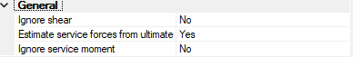
Ignore Shear
Omit the horizontal shear force from the support reactions from the design of pad foundations. This reduces or omits applied bending on the pad. If you use this option you must be careful to remember to resist the horizontal forces by some other method. A typical example of this would be where the column leg is tied to the floor slab.
Estimate Service Forces from Ultimate cases
Where no matching service case is found, estimate the service forces from ultimate forces in corresponding ultimate case by reducing by an appropriate factor.
Ignore service moment
If there are no Ultimate moments then ignore any service moments. This applies to frames with “Nominally pinned” steel columns to BS 5950-1:2000 Cl 5.1.3.3 where 20% base fixity is allowed in service cases to reduce deflections.
Concrete
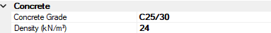
Density
Density of the concrete in kN/m3.
Reinforcement
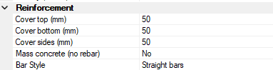
Mass Concrete
Design all pads as mass concrete.
Bar Style
Style of reinforcement , you can choose between
- Straight Bars.
- Bobbed Bars.
- Full height U-Bars.
Loads

Surcharge
Surcharge to top of base in kN/m2 applied to whole surface area of base.
Gk Service Factor
Partial safety factor on the Density and Surcharge in service load cases.
Gk Ultimate Factor
Partial safety factor on the Density and Surcharge in ultimate load cases.
Geotechnical
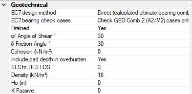
EC7 design Method
Eurocode 7 design method for Pad geotechnical design EC7 6.4(5)
EC7 Bearing Check Cases
Eurocode 7 bearing check cases. Usually combination 2 (A2/M2) Set C cases produce the critical bearing conditions.
Drained
Use drained soil condition for bearing pressure EC7 D4 otherwise undrained D3
Angle of shear
Angle of shear resistance in terms of effective stress
Friction Angle
Angle of friction
Cohesion
Cohesive shear resistance of base in kN/m2 10 to 140 kN/m2 for Soft to Stiff clays in Reynolds Table 17. Use with caution.
Include Pad depth in overburden
Include the pad depth in the overburden value q for bearing resistance calculation . EC7-1 Annex D
SLS to ULS FOS
Allowable serviceability bearing pressure factor pf safety from ultimate bearing resistance
Soil Density
If we have a soil density γs then we can increase your SWP by the overburden height H * γs. H=top of plinth to underside of base.
Height of soil Ho
Height of soil in m above pad - used for calculating passive pressure & additional surcharge.
K Passive
Set the K passive factor.
Auto Design
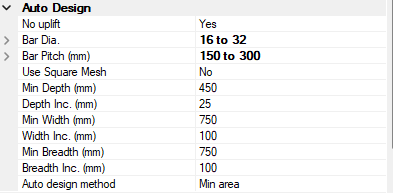
No up-lift
Size pads to prevent up-lift of the base. During Auto Design only.
Use square mesh
Max min range of bar gaps, tension only
Min Depth
Min depth of pad base during auto design.
Depth Inc.
Auto design increment of the pad depth
Min Width
Min width of pad base during auto design.
Width inc.
Min Breadth
Min breadth of pad base during auto design.
Breadth inc.
Auto design increment of the pad beradth
Auto design Method
Rebar auto design strategy
Labelling
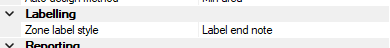
Zoned rebar pitch level style
Reporting
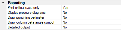
Print Critical Case Only
Display Pressure Diagram
Display or hide the base pressure diagram
Display Punching Perimeter
Display or hide the base punching perimeter at 1.5 D from column face
Draw Column Beta Angle Symbol
Draw the column's beta angle symbol on the corresponding pad graphic so as to check the orientation of the column and pad.
Detailed Output
Display (and print) or hide additional design information